Video switcher and video switching method

a video switcher and video technology, applied in the direction of color burst signal generation/insertion, television system, color television details, etc., can solve the problems of complex constitution of the switcher, increased initial cost of the system, distortion of displayed videos, etc., to reduce distortion of displayed videos and distortion of displayed videos

Inactive Publication Date: 2009-04-30
IMAGENICS
View PDF17 Cites 13 Cited by
  • Summary
  • Abstract
  • Description
  • Claims
  • Application Information

AI Technical Summary

Benefits of technology

[0013]According to the present invention, discontinuity of synchronization signals at the time of switching video sources is solved and distortion of displayed videos is reduced.
[0014]In addition, according to the present invention, switching timing of the video sources can be set in accordance with properties of the video display unit (performance characteristics) so that the distortion of displayed videos can be reduced.

Problems solved by technology

The distortion of the displayed videos is caused by discontinuity of synchronization signals from the video sources.
A frame synchronizer is present as a device for dissolving the discontinuity of the synchronization signals, but since it is very expensive, the initial cost for the system rises drastically.
According to the proposal of JP-A 6-149181, however, a unit for setting video signals to be switched to a black level is necessary, and thus the constitution of the switcher becomes complicated and thus the cost rises.
The proposal of JP-A 6-133234, on the other hand, does not solve the discontinuity at the time of switching the synchronization signals separated from the video signals before and after switching.

Method used


Image

  • Video switcher and video switching method
  • Video switcher and video switching method
  • Video switcher and video switching method

Examples


Embodiment Construction

[0019]A video switcher and a video switching method according to an embodiment of the present invention will be described below with reference to the drawings.

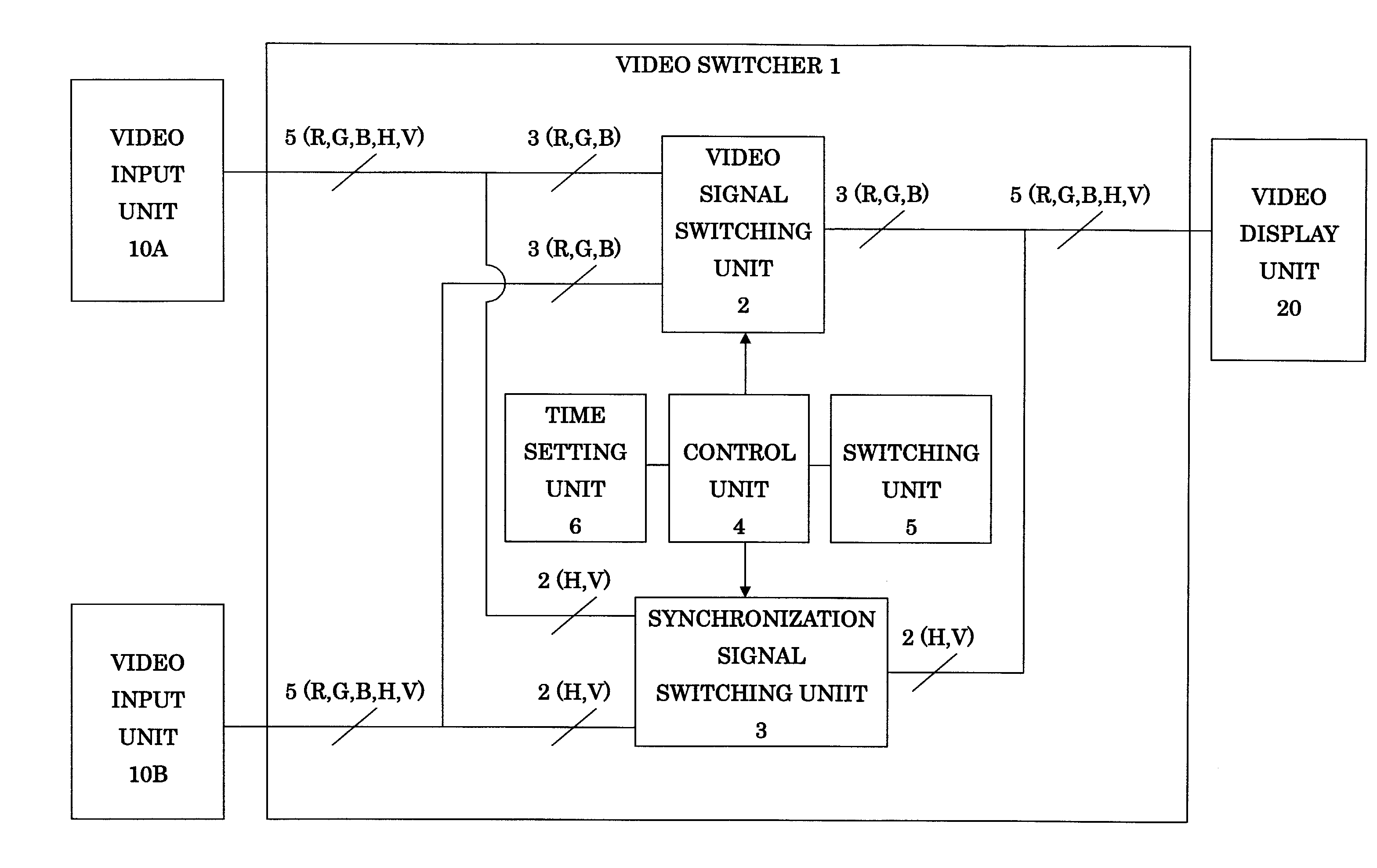
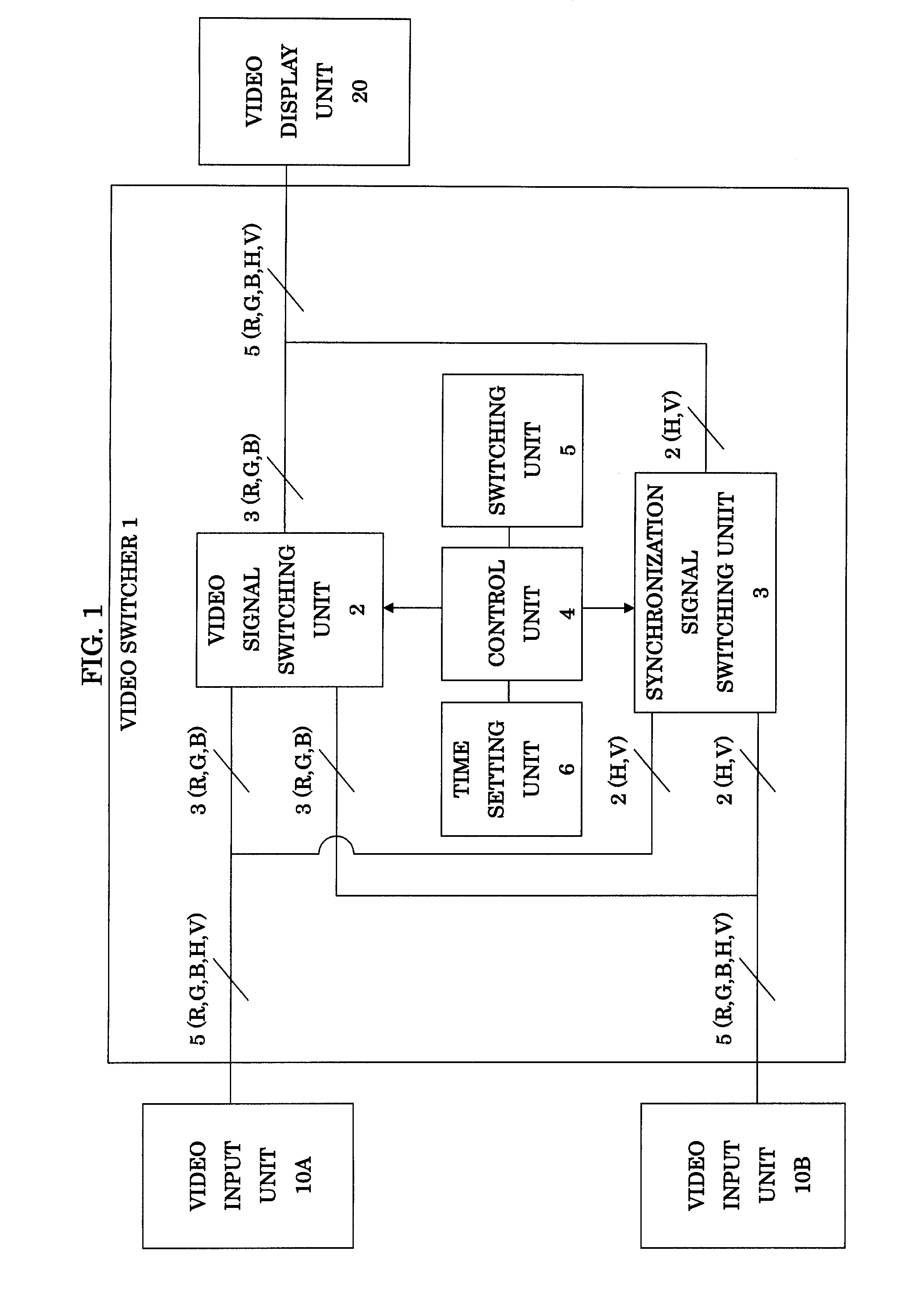
[0020]FIG. 1 is a block diagram illustrating the video switcher according to the embodiment of the invention. The video switcher 1 includes a video signal switching unit 2, a synchronization signal switching unit 3, a control unit 4, a switching unit 5, and a time setting unit 6.

[0021]A video input unit 10A and a video input unit 10B are connected to the video switcher 1. Video signals and synchronization signals corresponding to the video signals are supplied from the video input units to the video switcher 1. FIG. 1 illustrates an example where the video signals (R, G, B) and the synchronization signals (H, V) are supplied from the video input units to the video switcher 1.

[0022]Also, a video display unit 20 is connected to the video switcher 1. The video switcher 1 supplies the video signal and the synchronization signal fr...


PUM


Abstract

A video switcher includes: a video signal switching device for switching a video signal to be transmitted to a video display unit from a first video signal supplied from a first video input unit into a second video signal supplied from a second video input unit; and a synchronization signal switching device for switching a synchronization signal to be transmitted to the video display unit from a first synchronization signal supplied from the first video input unit into a second synchronization signal supplied from the second video input unit. The synchronization signal switching device starts transmission of the second synchronization signal to the video display unit after stops transmission of the first synchronization signal to the video display unit. The video signal switching device starts transmission of the second video signal to the video display unit, after stop of transmission of the first video signal to the video display unit and start of transmission of the second synchronization signal to the video display unit.

Description

BACKGROUND OF THE INVENTION[0001]1. Field of the Invention[0002]The present invention relates to a video switcher and a video switching method for selecting one video from a plurality of videos supplied from a plurality of video input units so as to output the selected video to a video display unit, and particularly reduce distortion of a displayed video at the time of switching videos.[0003]2. Description of the Related Art[0004]In video switchers which switch videos from a plurality of video input units (video sources) and simultaneously output the videos to video display units, displayed videos are distorted at the time of switching video sources. The distortion of the displayed videos is caused by discontinuity of synchronization signals from the video sources. The discontinuity of the synchronization signals occurs when the respective video sources operate independently and they are switched. A frame synchronizer is present as a device for dissolving the discontinuity of the sy...

Claims


Application Information

Patent Timeline
Patent Type & Authority Applications(United States)
IPC IPC(8): H04N5/04H04N5/268
CPCH04N5/268H04N5/04
Inventor MURAKAMI, NOBUYUKI
Owner IMAGENICS
Why Eureka
Try Eureka