

Optical system and image pickup apparatus using the same
a technology of optical system and image pickup, applied in the field of optical system, can solve the problems of large amount of various aberrations, and large amount of various aberrations, and achieve the effect of correcting spherical aberrations
- Summary
- Abstract
- Description
- Claims
- Application Information
AI Technical Summary
Benefits of technology
Problems solved by technology
Method used
Image

Examples
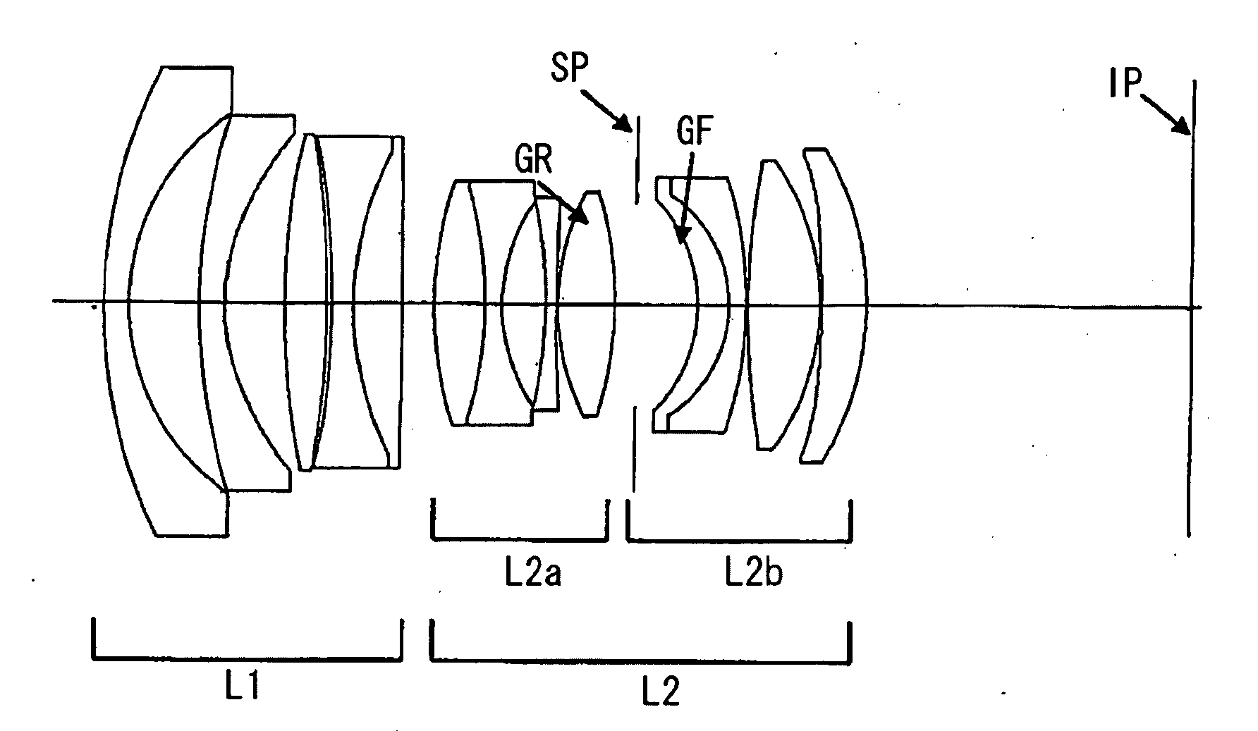
numerical example 1
[0066]
L1r1 = 61.880d1 = 2.994nd1 = 1.83481νd1 = 42.72r2 = 27.026d2 = 8.344r3 = 71.747d3 = 3.000nd2 = 1.58313νd2 = 59.40r4* = 25.706d4 = 6.931r5 = 92.706d5 = 4.947nd3 = 1.88300νd3 = 40.76r6 = −127.713d6 = 0.697r7 = −97.467d7 = 2.500nd4 = 1.49700νd4 = 81.54r8 = 39.023d8 = 5.825nd5 = 1.83481νd5 = 42.72r9 = −1070.546d9 = 3.788L2ar10 = 46.333d10 = 5.979nd6 = 1.83481νd6 = 42.72r11 = −47.248d11 = 1.900nd7 = 1.54814νd7 = 45.79r12 = 21.482d12 = 5.068r13 = −53.687d13 = 1.400nd8 = 1.65412νd8 = 39.70r14 = 197.561d14 = 0.150r15 = 29.239d15 = 6.730nd9 = 1.43387νd9 = 95.10r16 = −44.333d16 = 2.594L2br17 = stopd17 = 7.213r18 = −17.904d18 = 3.777nd10 = 1.60311νd10 = 60.64r19 = −15.383d19 = 2.150nd11 = 1.80518νd11 = 25.42r20 = −48.206d20 = 0.250r21 = 97.922d21 = 8.536nd12 = 1.61800νd12 = 63.33r22 = −29.308d22 = 0.250r23* =d23 = 5.284nd13 = 1.80400νd13 = 46.57−162.434r24 = −36.488d24 =38.799Aspheric Coefficientsr4c4 = −5.57660E−06c6 = −9.40593E−09c8 = 5.84551E−12c10 = −3.17028E−14r23c4 = −1.09975E−05c6...
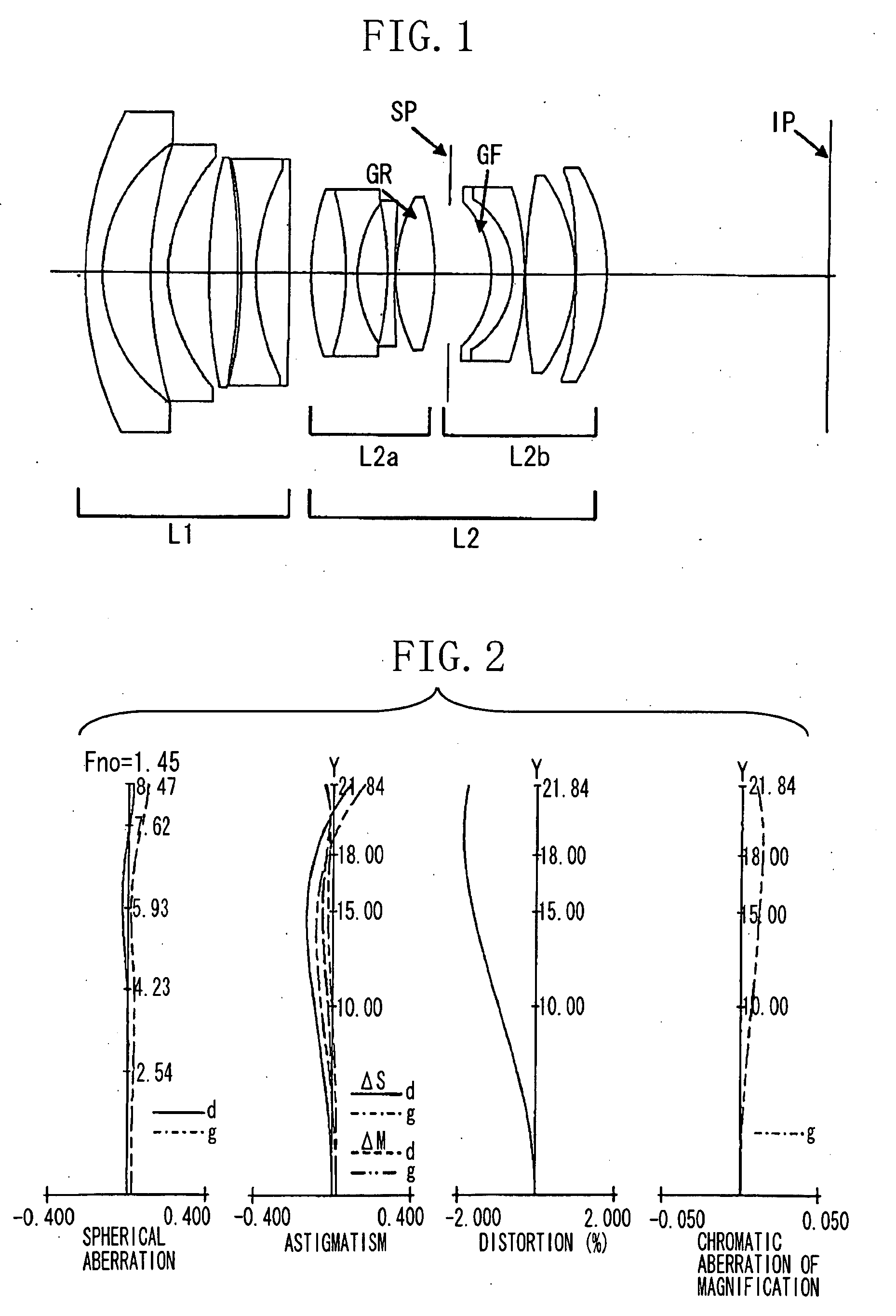
numerical example 2
[0067]
L1r1 = 60.645d1 = 2.994nd1 = 1.83481νd1 = 42.72r2 = 27.012d2 = 8.000r3 = 117.341d3 = 3.000nd2 = 1.58313νd2 = 59.40r4* = 23.272d4* = 5.954r5 = 45.007d5 = 5.975nd3 = 1.88300νd3 = 40.76r6 = −181.809d6 = 3.691L2ar7 = 37.305d7 = 4.803nd4 = 1.83481νd4 = 42.72r8 = −220.690d8 = 1.900nd5 = 1.49700νd5 = 81.54r9 = 18.219d9 = 5.662r10 = −50.884d10 = 1.400nd6 = 1.65412νd6 = 39.70r11 = 108.422d11 = 0.150r12 = 27.172d12 = 7.637nd7 = 1.49700νd7 = 81.54r13 = −35.855d13 = 2.999L2br14 = stopd14 = 7.090r15 = −17.372d15 = 3.725nd8 = 1.80400νd8 = 46.57r16 = −15.383d16 = 2.150nd9 = 1.80518νd9 = 25.42r17 = −54.381d17 = 0.250r18 = 77.012d18 = 8.895nd10 = 1.59240νd10 = 68.30r19 = −29.139d19 = 0.250r20* =d20 = 4.597nd11 = 1.80400νd11 = 46.57−146.547r21 = −37.218d21 =38.012Aspheric Coefficientsr4c4 = −7.07218E−06c6 = −1.52849E−08c8 = 1.49643E−11c10 = −7.71857E−14r20c4 = −1.18658E−05c6 = −2.84003E−09c8 = −1.17097E−11c10 = −7.45942E−15Various DataFocal Length24.55F-number1.45Image Height21.64Lens Total81.1...
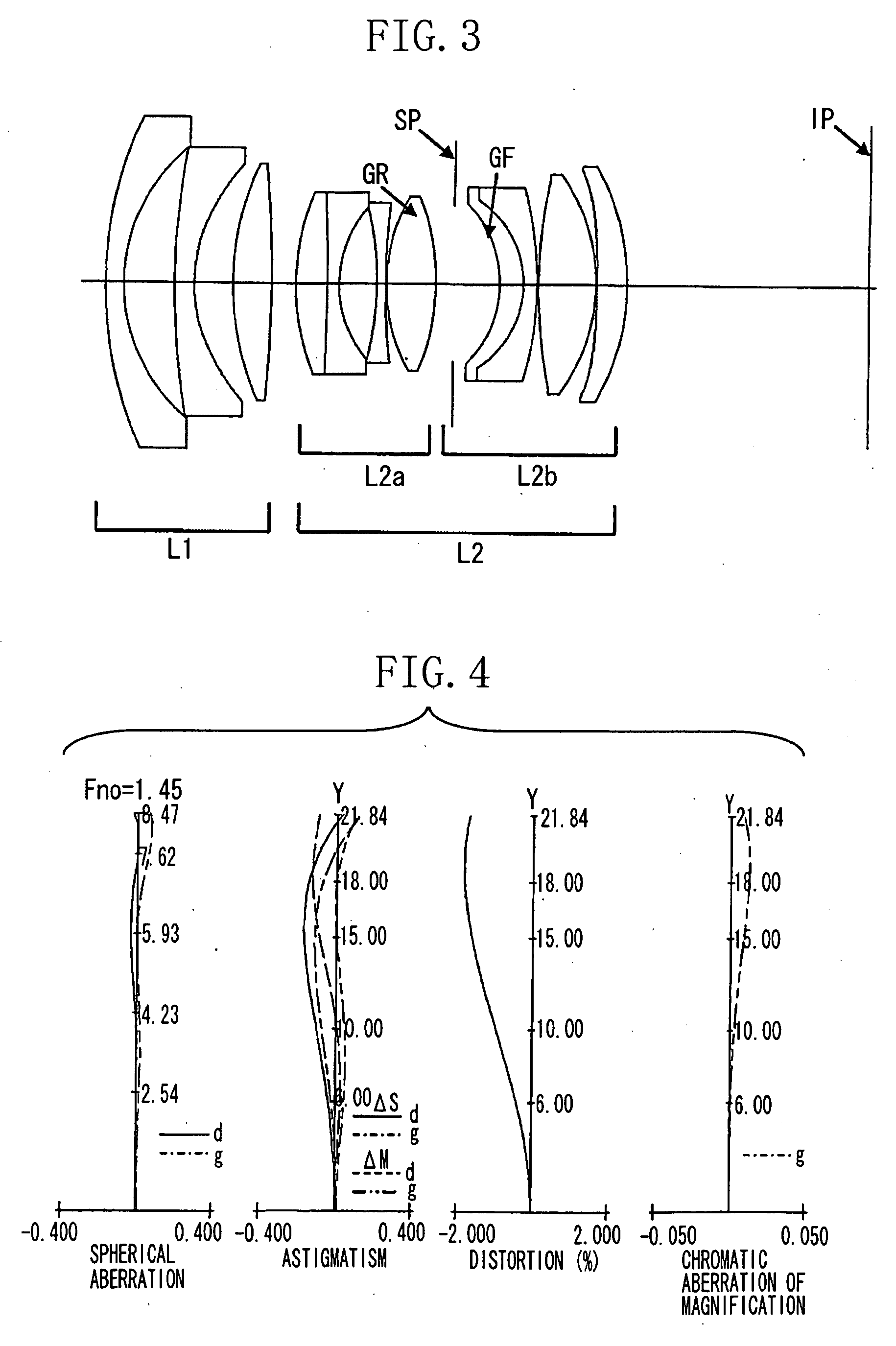
numerical example 3
[0068]
L1r1 = 59.063d1 = 2.994nd1 = 1.83481νd1 = 42.72r2 = 27.010d2 = 7.815r3 = 68.210d3 = 3.000nd2 = 1.58313νd2 = 59.40r4* = 24.275d4 = 7.599r5 = 108.731d5 = 4.852nd3 = 1.88300νd3 = 40.76r6 = −108.705d6 = 1.526r7 = −66.658d7 = 2.500nd4 = 1.49700νd4 = 81.54r8 = 32.662d8 = 7.321nd5 = 1.83481νd5 = 42.72r9 = −172.465d9 = 8.840L2ar10 = 547.204d10 = 5.324nd6 = 1.83481νd6 = 42.72r11 = −27.839d11 = 1.900nd7 = 1.65412νd7 = 39.70r12 = 29.617d12 = 0.875r13 = 25.336d13 = 5.618nd8 = 1.49700νd8 = 81.54r14 = −411.804d14 = 4.090L2br15 = stopd15 = 6.627r16 = −17.992d16 = 3.205nd9 = 1.80400νd9 = 46.57r17 = −16.912d17 = 2.150nd10 = 1.80518νd10 = 25.42r18 = −67.130d18 = 0.250r19 = 86.485d19 = 8.071nd11 = 1.61800νd11 = 63.33r20 = −29.407d20 = 0.250r21* =d21 = 5.300nd12 = 1.80400νd12 = 46.57−231.324r22 = −37.889d22 =38.009Aspheric Coefficientsr4c4 = −6.72766E−06c6 = −1.54205E−08c8 = 2.34607E−11c10 = −6.75849E−14r21c4 = −1.10021E−05c6 = −3.10945E−09c8 = −6.17052E−12c10 = −1.02038E−14Various DataFocal Leng...
PUM
 Abstract
Description
Claims
Application Information