Eureka AIR delivers breakthrough ideas for toughest innovation challenges, trusted by R&D personnel around the world.

Variable-power optical system, image pickup device, and digital apparatus

a technology of optical system and image pickup, applied in the field of variable-power optical system, image pickup device, digital apparatus, can solve the problems of insufficient correction of astigmatism and chromatic aberration, severe size and cost restrictions, increased costs, etc., to achieve effective correction, compact configuration, and reduce costs

Active Publication Date: 2010-02-25
KONICA MINOLTA OPTO
View PDF13 Cites 13 Cited by
  • Summary
  • Abstract
  • Description
  • Claims
  • Application Information

AI Technical Summary

Benefits of technology

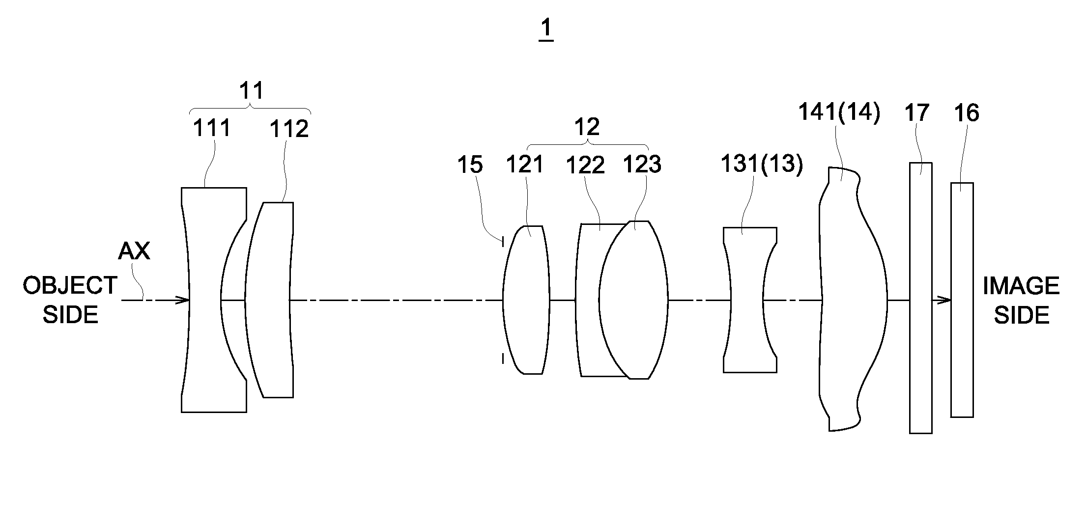
[0034]This configuration is provided as a so-called negative-lead optical system, in which the first lens group located closest to the object has a negative optical power. This ensures that a quick reduction in angle of light coming from the object side at a large angle is provided by the negative optical power of the first lens group, and the overall optical length and the front lens diameter are reduced in terms of size, which are advantageous. Further, in the negative-lead configuration, an increase in error sensitivity can be reduced even when a compact configuration of the optical system is achieved. These advantages are conspicuous in a zoom lens having a variable-power ratio of about 2 to 4 times. Further, use of a negative-positive-negative-positive four-component arrangement ensures compact configuration of the variable-power optical unit resulting from reduced traveling distance at the time of varying the power, excellent telecentricity, and satisfactory correction of spherical aberration, chromatic aberration and astigmatism. Further, at least one aspheric surface is included in the second lens group. This arrangement corrects a spherical aberration which increases as the optical power of the second lens group increases.
[0080]The present invention provides a variable-power optical system of sufficiently compact configuration exhibiting effective correction of aberrations over the overall variable-power range. It provides, in particular, a variable-power optical system having a variable-power ratio of about 2 to 4 times, and an image pickup device or digital apparatus carrying the same at reduced costs with sufficiently miniaturized configuration.

Problems solved by technology

These devices are characterized by severe restrictions on the size and cost.
In the disclosed optical system, however, a power arrangement in the first lens group and lens materials in the second lens group are not optimized, and correction of astigmatism and chromatic aberration becomes insufficient.
However, this system contains a prism for bending the optical axis, and this results in increased costs.
Although an attempt for thin configuration has been made, the overall length of the optical system is excessive, and efforts toward compact configuration are insufficient in terms of unit volume.
However, this arrangement entails the disadvantages of an increase in the number of movable lens groups, and insufficient correction of spherical aberration and astigmatism.
More compact configuration of the variable-power optical system is difficult.

Method used


Image

  • Variable-power optical system, image pickup device, and digital apparatus
  • Variable-power optical system, image pickup device, and digital apparatus
  • Variable-power optical system, image pickup device, and digital apparatus

Examples


example 1

[0209]FIG. 4 is a cross sectional view (optical path diagram) traversing the optical axis AX, representing the arrangement of lens groups in the variable-power optical system 1A of Example 1. The optical path diagrams of FIG. 4 and FIG. 5 through 15 show the lens arrangement at the wide-angle end (W). Throughout Example 1 and Examples 2 through 12 to be described below, these lens groups include a first lens group (Gr1) having a negative optical power as a whole, a second lens group (Gr2) having a positive optical power, a third lens group (Gr3) having a negative optical power, and a fourth lens group (Gr4) having a positive optical power, in that order as viewed from the object side in the drawings (the left side in FIG. 4). To put it another way, the lens groups are aligned in a negative-lead configuration wherein the first lens (Gr1) closest to the object has a negative optical power and are provided as a four-component variable-power optical system with negative, positive, negat...

example 2

[0223]FIG. 5 is a cross sectional view traversing the optical axis (AX), representing the arrangement of the lens groups in the variable-power optical system 1B in Example 2. The variable-power optical system 1B in Example 2 includes a first lens group (Gr1) having a negative optical power as a whole, an optical stop (ST), a second lens group (Gr2) having a positive optical power as a whole, a third lens group (Gr3) having a negative optical power, and a fourth lens group (Gr4) having a positive optical power, in that order as viewed from the object side. To put it in more detail, the first lens group (Gr1) is composed of a biconcave negative lens (L1) and a positive meniscus lens (L2) with a convex surface facing the object side, in that order as viewed from the object side. The second lens group (Gr2) is composed of a biconvex positive lens (L3) and a biconcave negative lens (L4) arranged in that order as viewed from the object side. The third lens group (Gr3) is composed of one n...

example 3

[0226]FIG. 6 is a cross sectional view traversing the optical axis (AX), representing the arrangement of the lens group in the variable-power optical system 1C of Example 3. The variable-power optical system 1C of Example 3 includes a first lens group (Gr1) having a negative optical power as a whole, an optical stop (ST), a second lens group (Gr2) having a positive optical power as a whole, a third lens group (Gr3) having a negative optical power, and a fourth lens group (Gr4) having a positive optical power, in that order as viewed from the object side. To put it in more detail, the first lens group (Gr1) is composed of a biconcave negative lens (L1) and a positive meniscus lens (L2) with a convex surface with the object side, in that order as viewed from the object side. The second lens group (Gr2) is composed of a biconvex positive lens (L3) and a biconcave negative lens (L4), in that order as viewed from the object side. The third lens group (Gr3) is composed of one negative men...


PUM


Abstract

A variable-power optical system includes, in order from an object side thereof: a first lens group with a negative optical power; a second lens group with a positive optical power; a third lens group with a negative optical power; and a fourth lens group with a positive optical power. An interval between the first lens group and the second lens group decreases when a power of the variable-power optical system varies from a wide-angle end to a telephoto end. The second lens group includes at least one aspheric surface. The variable-power optical system satisfies the predetermined conditional expressions.

Description

TECHNICAL FIELD[0001]The present invention relates to a variable-power optical system including a plurality of lens groups wherein power is varied by changing a space between lens groups in an optical axis direction, an image pickup device equipped with this variable-power optical system, and a digital apparatus with this image pickup device mounted thereon, particularly to a variable-power optical system suited for extremely miniaturized configurations.BACKGROUND ART[0002]In recent years, there has been a remarkable spread of mobile phones and PDAs (Personal Digital Assistant). It has become a common practice to incorporate a compact digital still camera unit and digital video unit in such devices. These devices are characterized by severe restrictions on the size and cost. Therefore, there has been generally used a small-sized image pickup device equipped with a smaller number of pixels than that in a normal digital still camera, and a unifocal optical system including about one t...

Claims


Application Information

Patent Timeline
IPC IPC(8): H04N5/225G02B15/14
CPCG02B15/177G02B15/144511
Inventor MATSUSAKA, KEIJIOHZAWA, SOHFUKUTA, YASUNARI
Owner KONICA MINOLTA OPTO
Why Eureka
Eureka Blog
Learn More