Refrigerant compressor arrangement

a compressor and refrigerant technology, applied in the direction of machines/engines, liquid fuel engines, positive displacement liquid engines, etc., can solve the problems of user inconvenience and other problems, and achieve the effect of saving weigh

Inactive Publication Date: 2009-04-30
SECOP GMBH +1
View PDF6 Cites 5 Cited by
  • Summary
  • Abstract
  • Description
  • Claims
  • Application Information

AI Technical Summary

Benefits of technology

[0018]Preferably, the recesses are open in the direction of the circumferential wall of the holder. Also this is a further measure for saving weight.
[0019]Preferably, the holder is made of an electrically isolating plastic material. Thus, it is avoided that currents from the compressor unit, particularly from the motor of the compressor unit, can reach the case via the holder and the spring. Thus, a danger for third parties is avoided.

Problems solved by technology

This is particularly the case for a frequency range around 800 Hz, which is particularly inconvenient for a user.

Method used


Image

  • Refrigerant compressor arrangement
  • Refrigerant compressor arrangement
  • Refrigerant compressor arrangement

Examples


Embodiment Construction

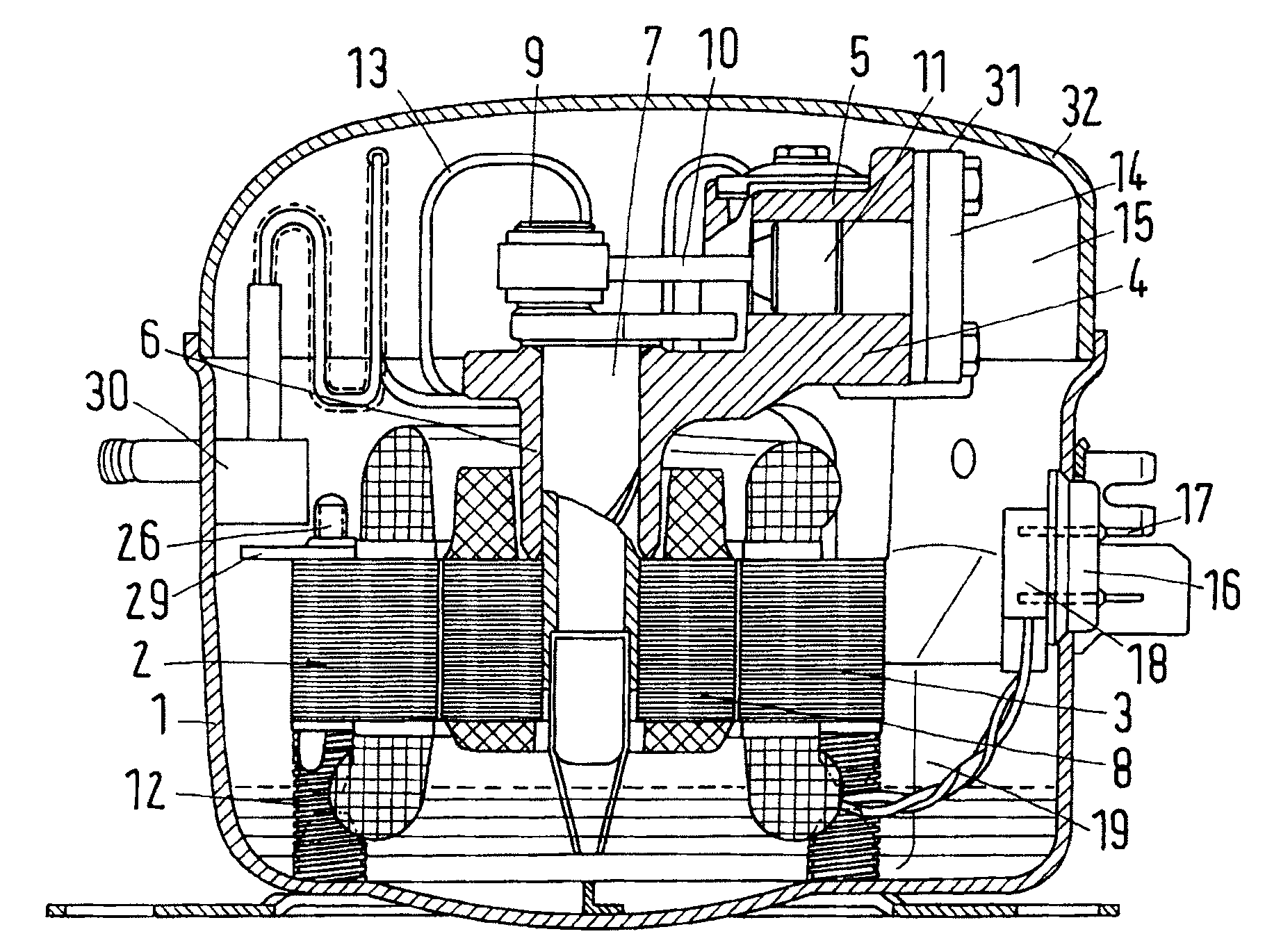
[0027]A compressor unit 2 is arranged in a case 1. A compressor housing 4 is connected to a stator 3 of an electric motor, the compressor housing 4 comprising a cylinder 5 and a bearing 6. In the bearing 6 a motor shaft 7 is supported, which carries a rotor 8 and drives a piston 11 via a crank pin 9 and a connecting rod 10, the piston 11 reciprocating in the cylinder 5. Helical compression springs 12 provide an elastic support for the compressor unit 2 in the case 1. Also a pressure pipe 13 is made to be elastic.

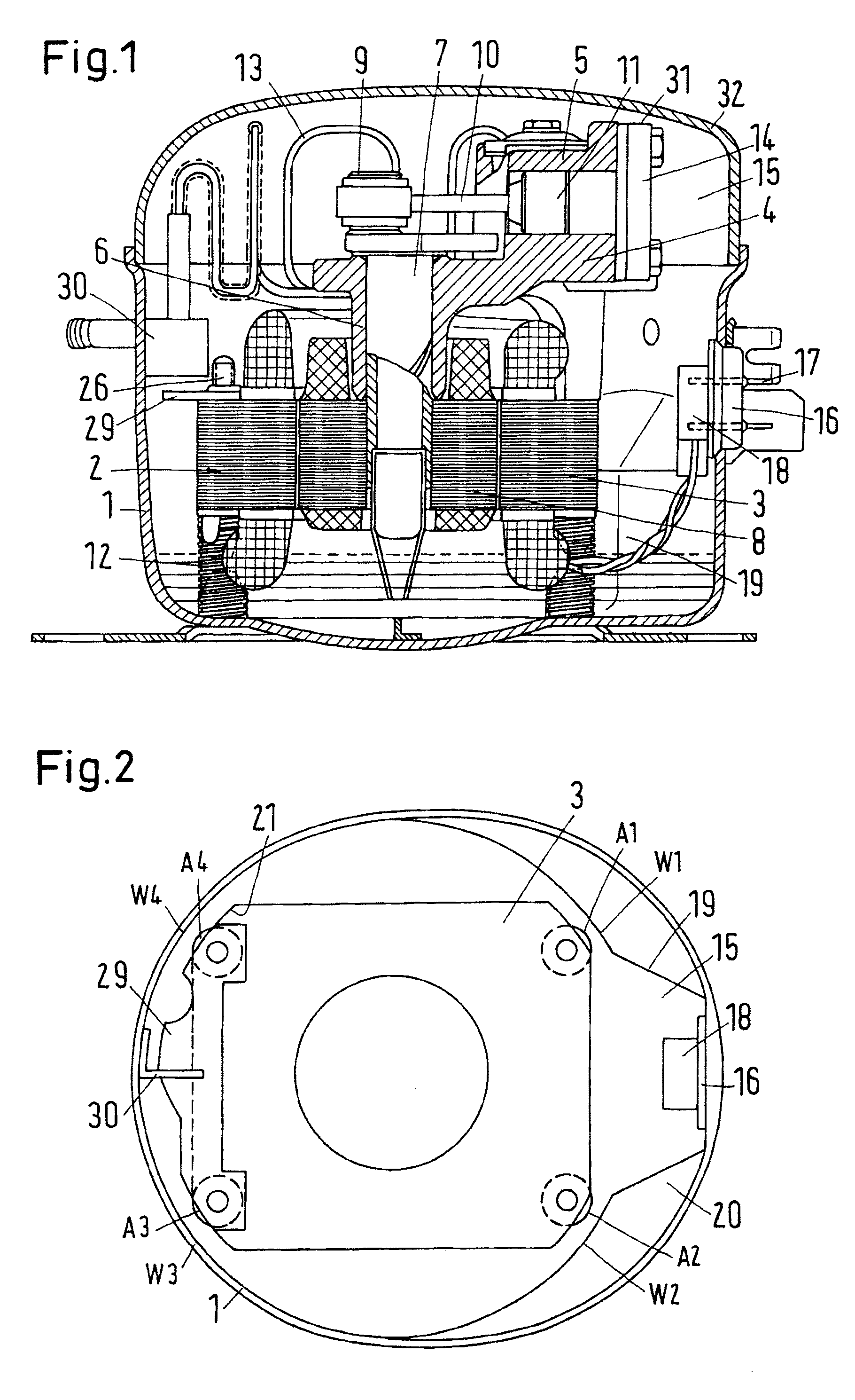
[0028]For adopting a cylinder head 14 projecting radially over the stator 3, an enlargement 15 is provided in the case 1. This enlargement also comprises an electric bushing 16 with bushing pins 17, whose inner ends carry a plug 18. In the bottom part of the case 1, both sides of the bushing 16 are provided with concavities 19 and 20. In this way, the wall of the case 1 forms four abutments W1-W4, which can interact with four stops A1-A4, which are arranged on the compressor...


PUM


Abstract

The invention concerns a refrigerant compressor arrangement with a compressor unit (2) supported in a case by means of springs (12) and comprising at least one bolt (26) with a bolt head (25), a holder (23) being arranged between the compressor unit (2) and at least one spring (12), the holder (23) having in its front a recess, in which the bolt head (25) engages, and which is connected to the spring (12). It is endeavoured to reduce the noise generation during operation of the refrigerant compressor arrangement. For this purpose, the bolt head (25) is arranged in the recess (24) with lateral clearance (34).

Description

CROSS REFERENCE TO RELATED APPLICATION[0001]Applicant hereby claims foreign priority benefits under U.S.C. § 119 from German Patent Application No. 10 2007 048 936.8 filed on Oct. 12, 2007, the contents of which are incorporated by reference herein.FIELD OF THE INVENTION[0002]The invention concerns a refrigerant compressor arrangement with a compressor unit supported in a case by means of springs and comprising at least one bolt with a bolt head, a holder being arranged between the compressor unit and at least one spring, the holder having in its front a recess, in which the bolt head engages, and which is stuck together with the spring.BACKGROUND OF THE INVENTION[0003]Such a refrigerant compressor arrangement is known from, for example, U.S. Pat. No. 4,106,881. The compressor unit has an electric motor with a vertically extending shaft. Above the motor a compressor is arranged, which comprises a piston reciprocating in a cylinder. The piston is driven by the rotary movement of the ...

Claims


Application Information

Patent Timeline
Patent Type & Authority Applications(United States)
IPC IPC(8): F04C15/00
CPCF04B39/127F04B39/0044
Inventor OUTZEN, SVEND ERIKNISSEN, JENS ERIKPETERSEN, CARSTEN
Owner SECOP GMBH
Why Eureka
Try Eureka