Battery pack and battery pack separator

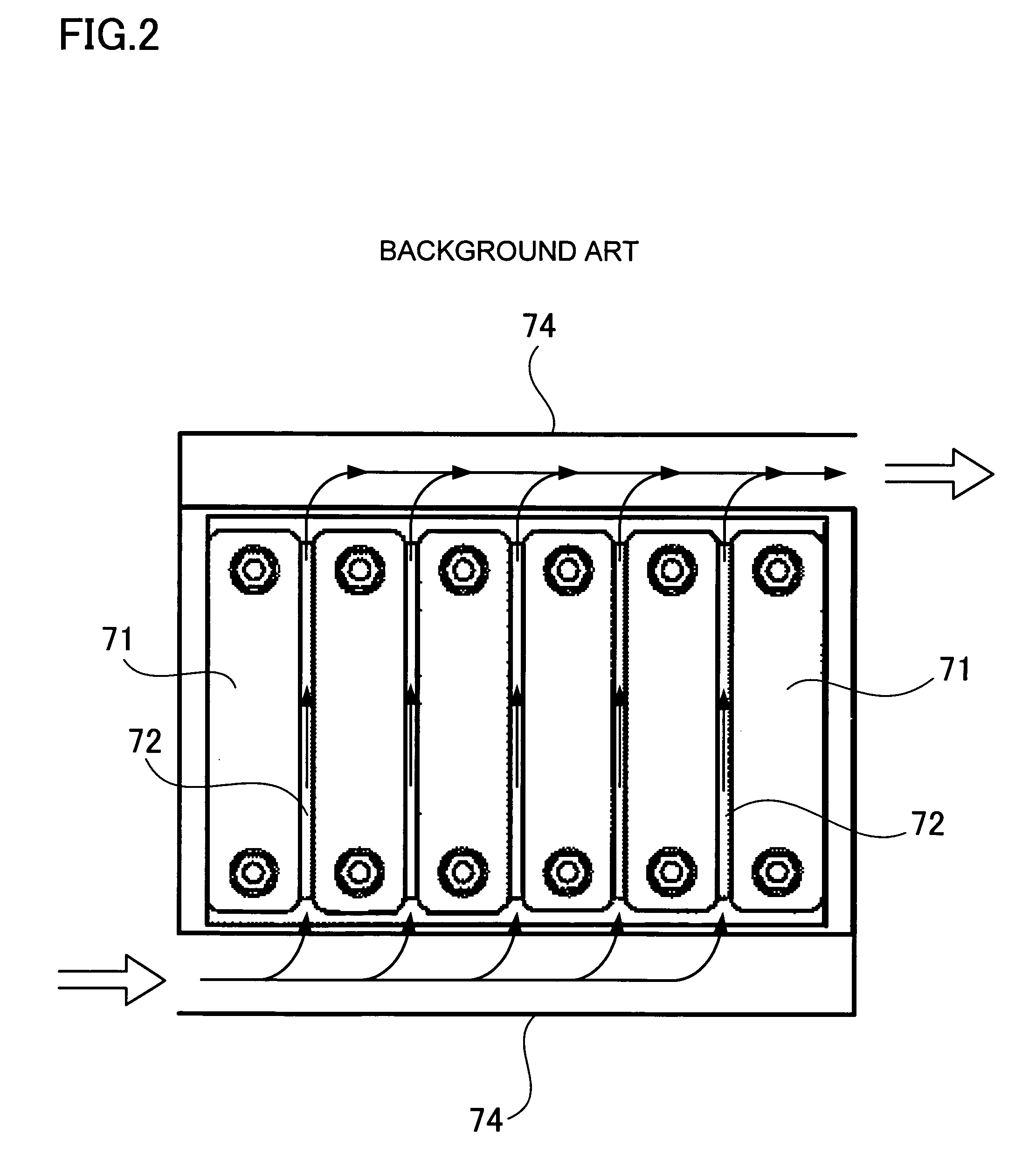
a battery pack and separator technology, applied in the direction of nickel accumulators, cell components, primary cell maintenance/service, etc., can solve the problems of inability to achieve uniform cooling, difficult to develop temperature unevenness, and tendency to accumulate cooling air, so as to reduce the pressure difference between the input-side and the output-side, and reduce the loss of cooling gas pressur

Active Publication Date: 2009-04-30
SANYO ELECTRIC CO LTD
View PDF1 Cites 88 Cited by
  • Summary
  • Abstract
  • Description
  • Claims
  • Application Information

AI Technical Summary

Benefits of technology

[0019]Finally, the eleventh battery pack separator is an insulating separator inserted between adjacent battery cells, where a plurality of battery cells makes up the battery pack. A separator is provided with a plurality of gas channels that enable the flow of cooling gas. The gas channels have cooling gas entranceways and exit ways, which open at the sides of the battery block formed by the stacked battery cells. Furthermore, a separator has cut sections formed to position the entranceways and exit ways of the gas channels inward from t...

Problems solved by technology

However, uniform cooling of all battery cells 71 without developing temperature unevenness is difficult with this structure.
Since cooling capability at the output-side is less than cooling capability at the input-side, local differences in cooling capability develop between the two sides and uniform cooling cannot be achieved.
In particular, in the case of forced cooling where cooling air is introduced to the input-side ...

Method used


Image

  • Battery pack and battery pack separator
  • Battery pack and battery pack separator
  • Battery pack and battery pack separator

Examples


first embodiment

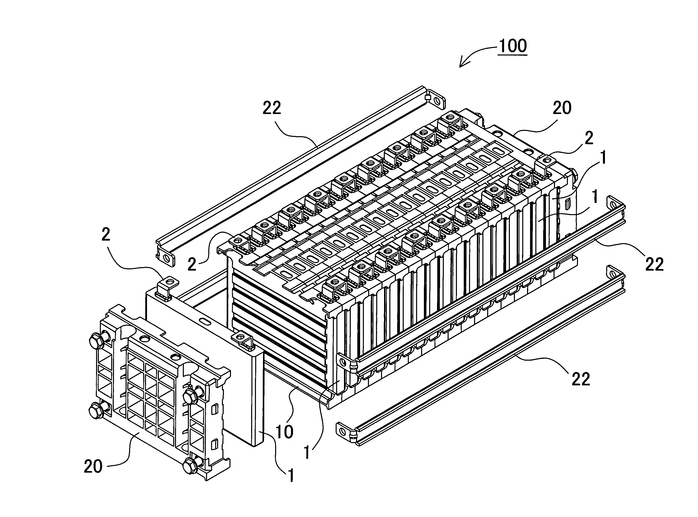
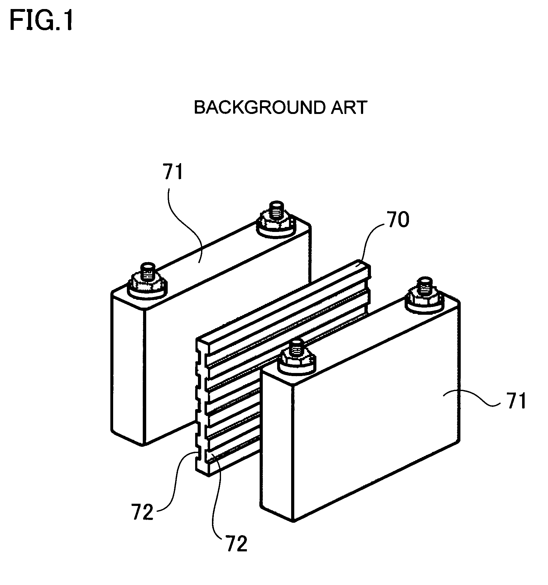
[0030]FIGS. 3 and 4 show an exploded oblique view of a battery pack 100 for the first form of embodiment of the present invention and an oblique view of a separator respectively. For comparison, FIGS. 5 and 6 show an exploded oblique view of a battery pack 500 that uses a prior art separator and an oblique view of that separator respectively. These battery packs are made up of battery blocks having a plurality of battery cells 1 stacked in the same orientation. Separators 10, 60 are sandwiched between adjacent battery cells 1. Endplates 20 are disposed at both ends of a battery block, and these endplates 20 are held in position, with the battery block in between, by lengthwise retaining rails 22.

[0031][Battery Block]

[0032]The battery block shown in FIG. 3 is a battery block for use on-board a car. The battery block is configured with a plurality of battery cells 1 and separators 10 stacked alternately and covered at the left and right ends by endplates 20. Specifically, rectangular ...

second embodiment

[0045]Next, a battery pack 200 for the second form of embodiment is shown in the exploded oblique view of FIG. 7, and its separator 10B is shown in the oblique view of FIG. 8. In the following description, elements that are identical to those of the first form of embodiment are labeled the same and their detailed description is abbreviated. In the second form of embodiment, the cut section CR2 of the separator 10B is further enlarged with a more concave center to give the separator 10B an hourglass shape. Specifically, the separator 10B is configured with corner regions SB2, center regions TR positioned laterally inward from the corner regions SB2, and sloped regions KR joining the corner regions SB2 and the center regions TR. In the example of FIG. 8, center regions TR have straight edges and the length of the separator 10B at its center is approximately one-third its height. Here, sloped regions KR also have straight edges. By giving the cut sections CR2 straight edge segments, se...

third embodiment

[0046]When battery cell swelling is small, even the separator of the second form of embodiment with its laterally narrow center region can maintain insulation between adjacent battery cells and prevent contact between those battery cells. In contrast, when severe battery cell expansion occurs, sufficient insulation may not be afforded by a laterally narrow center region. Consequently, there is concern that battery cells positioned on each side of a narrow separator could contact and short-circuit. In particular, since the battery cell surface carries an electric potential, a configuration is sought that can reliably insulate each battery cell and improve safety. To that end, the third form of embodiment shown in FIGS. 9 and 10 has a separator 10C with a wide lateral center region, which is the inverse of that of the second form of embodiment. Except for corner regions SB3, the left and right edges of the separator 10C are formed as convex (protruding) curves. FIG. 9 shows an explode...


PUM


Abstract

The battery pack includes plural battery cells 1, and insulating separators 10 disposed between adjacent battery cells 1, where the plurality of battery cells 1 are disposed in a stacked configuration with a prescribed gap between adjacent battery cells 1. A separator 10 has a plural gas channels that enable the flow of cooling gas. The gas channels have cooling gas entranceways and exit ways, which open at the sides of the battery block formed by the stacked battery cells 1. A separator 10 has cut sections formed to position the entranceways and exit ways of the gas channels inward from the sides of the battery block. This allows cooling gas near entranceways and exit ways to be smoothly introduced to, and exhausted from the gas channels, and reduces cooling gas pressure losses in those regions.

Description

BACKGROUND OF THE INVENTION[0001]1. Technical Field of the Invention[0002]The present invention relates to a battery pack and battery pack separator used in applications such as a car power source apparatus.[0003]2. Description of the Related Art[0004]In a car power source apparatus, many individual batteries (battery cells) are connected in series to increase output voltage and output power. Since this power source apparatus is charged and discharged with high currents, battery temperatures rise. Further, because the power source apparatus must be usable even in extreme high temperature environments, forced cooling of the batteries is essential. Power source apparatus on-board present day hybrid cars are cooled by forced ventilation of the batteries with cooling air delivered by fan. Since batteries in these power source apparatus are cooled by air, rapid cooling is difficult when abnormal battery temperature rise occurs. Further, because ventilation and cooling is via air, which h...

Claims


Application Information

Patent Timeline
IPC IPC(8): H01M10/50H01M10/60H01M10/613H01M10/617H01M10/625H01M10/643H01M10/647H01M10/652H01M10/6557H01M10/6563H01M10/658H01M50/209H01M50/291
CPCH01M2/1077H01M6/5038H01M10/0525H01M10/30H01M10/5004H01M10/5073H01M10/5032H01M10/5055H01M10/5059H01M10/5067H01M10/5016H01M10/613H01M10/625H01M10/647H01M10/6555H01M10/6557H01M10/6563H01M10/6566Y02E60/10H01M50/209H01M50/291
Inventor OKADA, WATARUNAKAMURA, SHINSUKE
Owner SANYO ELECTRIC CO LTD
Why Eureka
Try Eureka