
Connector

a technology of connecting rods and connectors, applied in the direction of incorrect coupling prevention, coupling device connection, electrical apparatus, etc., can solve the problems of plate-shaped pieces lacking rigidity, and achieve the effect of reducing the advance distance reliably preventing the advance of the mating connector into the hood, and enhancing the rigidity of the first prevention pi

Inactive Publication Date: 2009-04-30
SUMITOMO WIRING SYST LTD
View PDF10 Cites 7 Cited by
  • Summary
  • Abstract
  • Description
  • Claims
  • Application Information

AI Technical Summary

Benefits of technology

[0008]The second prevention pieces preferably are formed integrally with an inner peripheral surface of the hood. Thus, the second prevention pieces have a high rigidity and there is no fear that a pressing force applied by the mating connector will not deform the second prevention pieces.
[0014]The mating connector preferably is fit in the hood due to a cam action caused by rotation of a lever. Hence, the mating connector is likely to incline with respect to the hood about the rotational center of the lever while fitting the mating connector in the hood. Accordingly, the first and third prevention pieces preferably are spaced in the direction perpendicular to the rotational center of the lever and securely prevent the mating connector from inclining.

Problems solved by technology

However, a plate-shaped piece could lack rigidity.

Method used


Image

  • Connector
  • Connector
  • Connector

Examples


Embodiment Construction

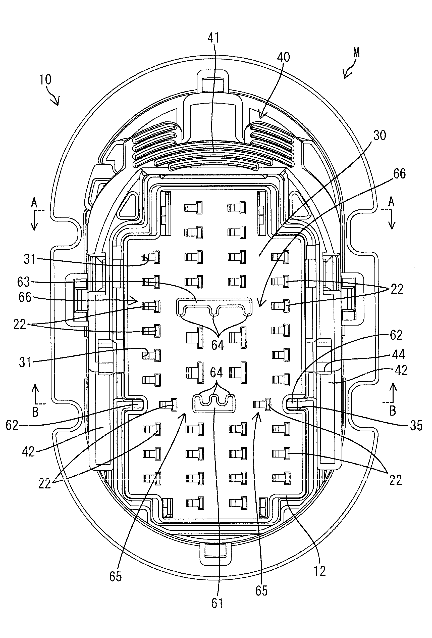
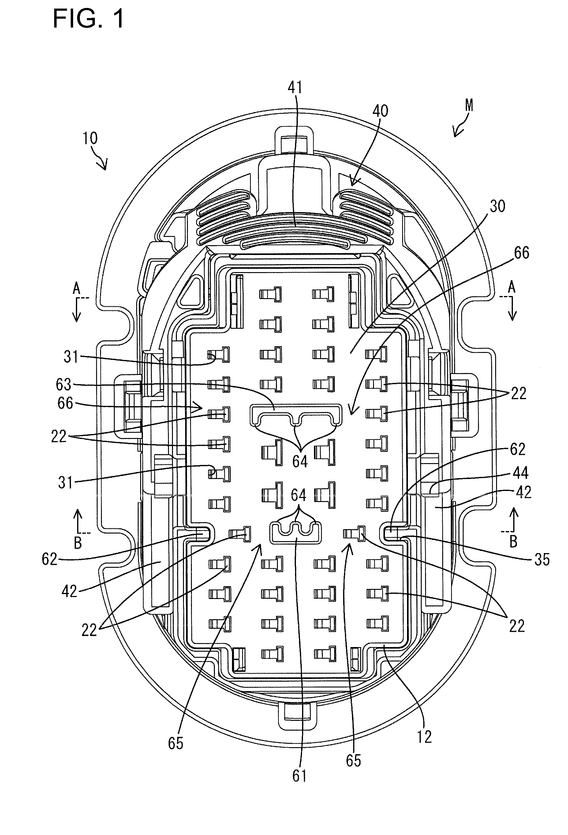
[0025]A male connector in accordance with the invention is identified by the letter M in FIGS. 1 through 9 and can be fit on a female connector F. The male connector M includes a male housing 10, a plurality of male terminal fittings 20, a front retainer 30 and a lever 40.

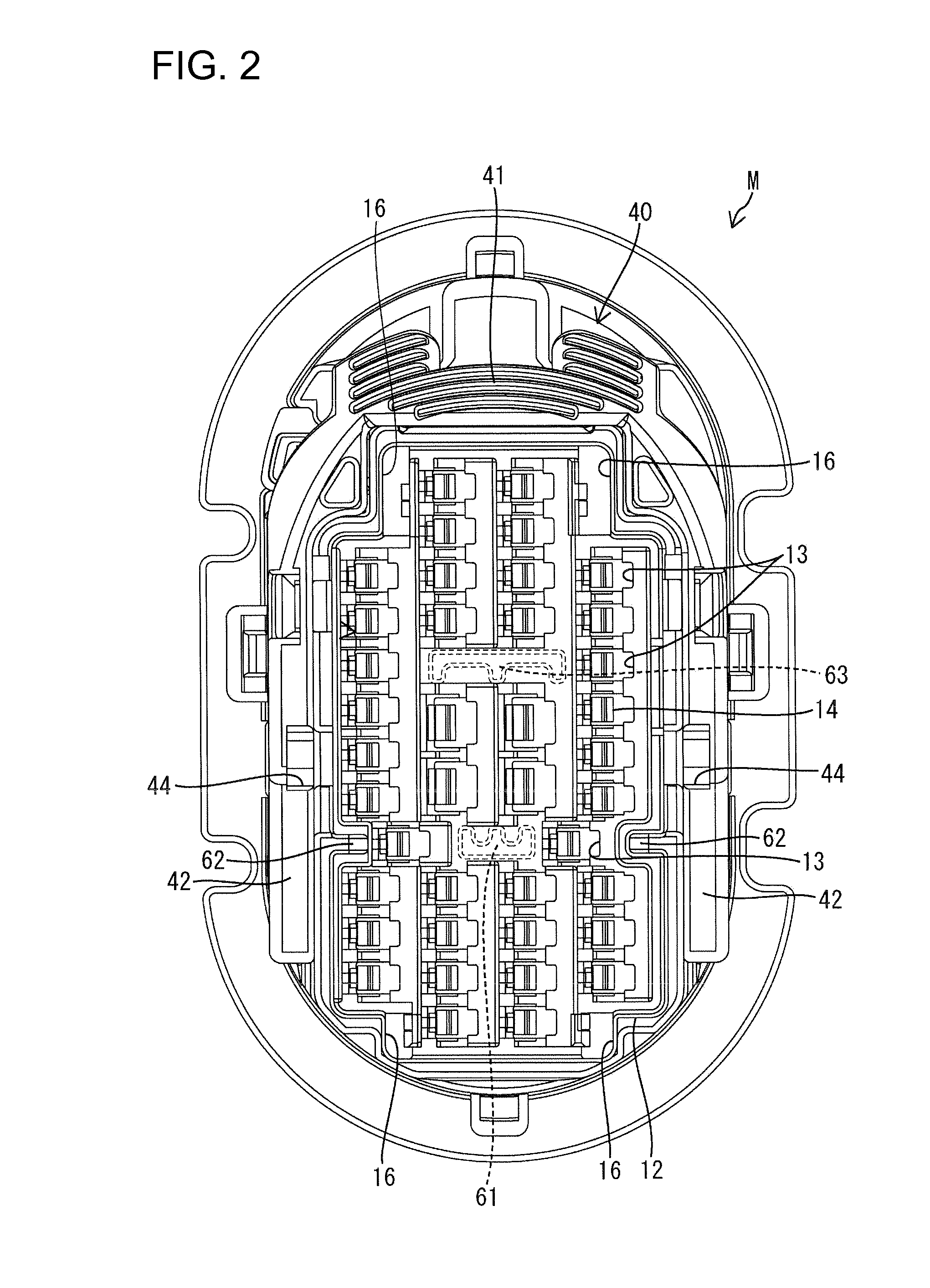
[0026]The male housing 10 is made of synthetic resin and includes a long narrow block-shaped terminal accommodation part 11 and a hood 12 that extends forward from a peripheral edge of the terminal accommodation part 11. The terminal accommodation part 11 and the hood 12 are formed unitarily with each other. Cavities 13 penetrate longitudinally through the terminal accommodation part 11 at predetermined positions in vertical and left-to-right directions. A lance 14 is cantilevered forward along an inner wall of each cavity 13, as shown in FIGS. 3 and 4, and a flexible space 15 is open on a front-end surface of the terminal accommodation part 11 to permit elastic flexure of the lance 14.

[0027]Four locking holes 16 a...


PUM


Abstract

A prevention part projected forward from a rear-end surface of a hood part (12) has a first prevention piece (61) disposed within a region of a rear-end surface of the hood part (12) from which a plurality of tabs (22) is projected; and a pair of second prevention pieces (62) so disposed as to sandwich the first prevention piece (61) therebetween, with the second prevention pieces (62) and the first prevention piece (61) arranged in a row at certain intervals. The tabs (22) are disposed between the first prevention piece (61) and the second prevention pieces (62). This construction is capable of decreasing a tab-disposing region.

Description

BACKGROUND OF THE INVENTION[0001]1. Field of the Invention[0002]The invention relates to a connector.[0003]2. Description of the Related Art[0004]Japanese Patent Application Laid-Open No. 2003-151682 discloses a connector with a terminal accommodation part. A hood extends forward from the terminal accommodation part and receives a mating connector. Tabs of the male terminal fittings project from the terminal accommodation part and are surrounded by the hood. A plate-shaped prevention part projects from the rear-end surface of the hood towards the open portion to prevent an obliquely aligned mating connector from interfering with the tabs as the mating connector is advanced into the hood.[0005]The tabs of the above-described connector are disposed vertically and horizontally on the rear end of the hood. The prevention part is long and extends continuously to divide the tabs into first and second groups so that the first-group tabs, the prevention part and the second-group tabs are ar...

Claims


Application Information

Patent Timeline
Patent Type & Authority Applications(United States)
IPC IPC(8): H01R13/44
CPCH01R13/64H01R13/62938
Inventor HIRAMATSU, HIROYUKI
Owner SUMITOMO WIRING SYST LTD
Learn More