Wireless communication apparatus and system employing the same apparatuses and method for controlling a plurality of the same apparatuses

a communication apparatus and a technology of a plurality of apparatuses, applied in the direction of electrical equipment, radio transmission, transmission monitoring, etc., can solve the problems of affecting affecting the reception of radio signals, so as to achieve the effect of reducing the level of radio signal input, and reducing the number of receivers

Active Publication Date: 2009-04-30
ICOM INC
View PDF14 Cites 0 Cited by
  • Summary
  • Abstract
  • Description
  • Claims
  • Application Information

AI Technical Summary

Benefits of technology

[0017]According to the wireless communication apparatus of the invention, the reception ability of the receiver is limited via the input portion when a reception limit signal is input from another wireless communication apparatus, and a radio signal transmitted from another nearby wireless communication apparatus such as a standby wireless communication apparatus is prevented from being received at too great of an intensity. The receivers can thereby be effectively protected.
[0018]According to another wireless communication apparatus of the invention, the power supply to the receiver is stopped when a reception limit signal is input from another wireless communication apparatus to the input portion, thereby making it possible to securely prevent a radio signal transmitted from another wireless communication apparatus from being received at too great of an intensity.
[0019]According to yet another wireless communication apparatus of the invention, when a reception limit signal is input from another wireless communication apparatus to the input portion, the signal attenuation means is activated to attenuate the receiver output level of the radio signal that is input to the receiver, allowing the minimum receiver function to be maintained.
[0020]According to a wireless communication system of the present invention in which at least two wireless communication apparatuses are used, and the out put portion of any one of those wireless communication apparatuses is connected to each input portions of the other wireless communication apparatuses, in cases where the plurality of wireless communication apparatuses are located in a relatively confined area, when a radio signal is transmitted from the transmitter of the currently used main wireless communication apparatus, a reception limit signal is transmitted from the output portion of the currently used wireless communication apparatus to the input portion of the nearby standby wireless communication apparatus, the reception ability of each receiver of the respective standby wireless communication apparatuses is limited, and unwanted noise is effectively prevented from being produced from the receiver of the respective standby wireless communication apparatuses on the basis of radio signal transmitted from the currently used wireless communication apparatus.
[0021]In addition, when a radio signal is transmitted from the currently used wireless communication apparatus, the signal attenuation means connected to the receiver of the standby wireless communication apparatus located near the main wireless communication apparatus is activated by the reception controller of the standby wireless communication apparatus to effectively attenuate the level of the radio signal input to the receiver from the main wireless communication apparatus, thereby effectively preventing unwanted noise or the like from being produced from the receiver of the stand wireless communication apparatus.

Problems solved by technology

In such cases, the signal strength from the main wireless communication apparatus will be too strong for the other adjacent standby wireless communication apparatus, and the receiver of the standby wireless communication apparatus may therefore become damaged.
Even if the receiver is not damaged, there have been problems in that the radio signals from the main wireless communication apparatus act as interference on the adjacent standby wireless communication apparatus.
Furthermore, even when a main wireless communication apparatus, i.e. a current wireless communication apparatus and at least one more standby wireless communication apparatuses are operated on unequal frequencies separately from each other, there have been problems in that a noise or voice sound is put out from the speaker of the standby apparatus due to spurious signals included in the signals transmitted from the main wireless communication apparatus.
However, no technique for eliminating the problems described above has been disclosed in the above-mentioned Patent Document 1 or the like, and in actuality users must resort to manually turning off the standby wireless communication apparatus, lowering the volume of the standby wireless communication apparatus, or the like, which is inconvenient.

Method used


Image

  • Wireless communication apparatus and system employing the same apparatuses and method for controlling a plurality of the same apparatuses
  • Wireless communication apparatus and system employing the same apparatuses and method for controlling a plurality of the same apparatuses
  • Wireless communication apparatus and system employing the same apparatuses and method for controlling a plurality of the same apparatuses

Examples


example 1

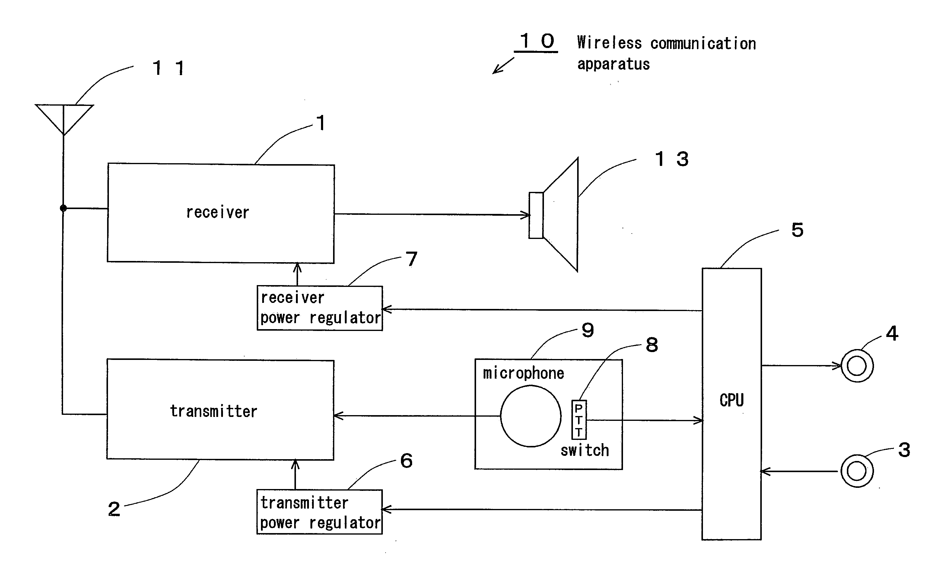
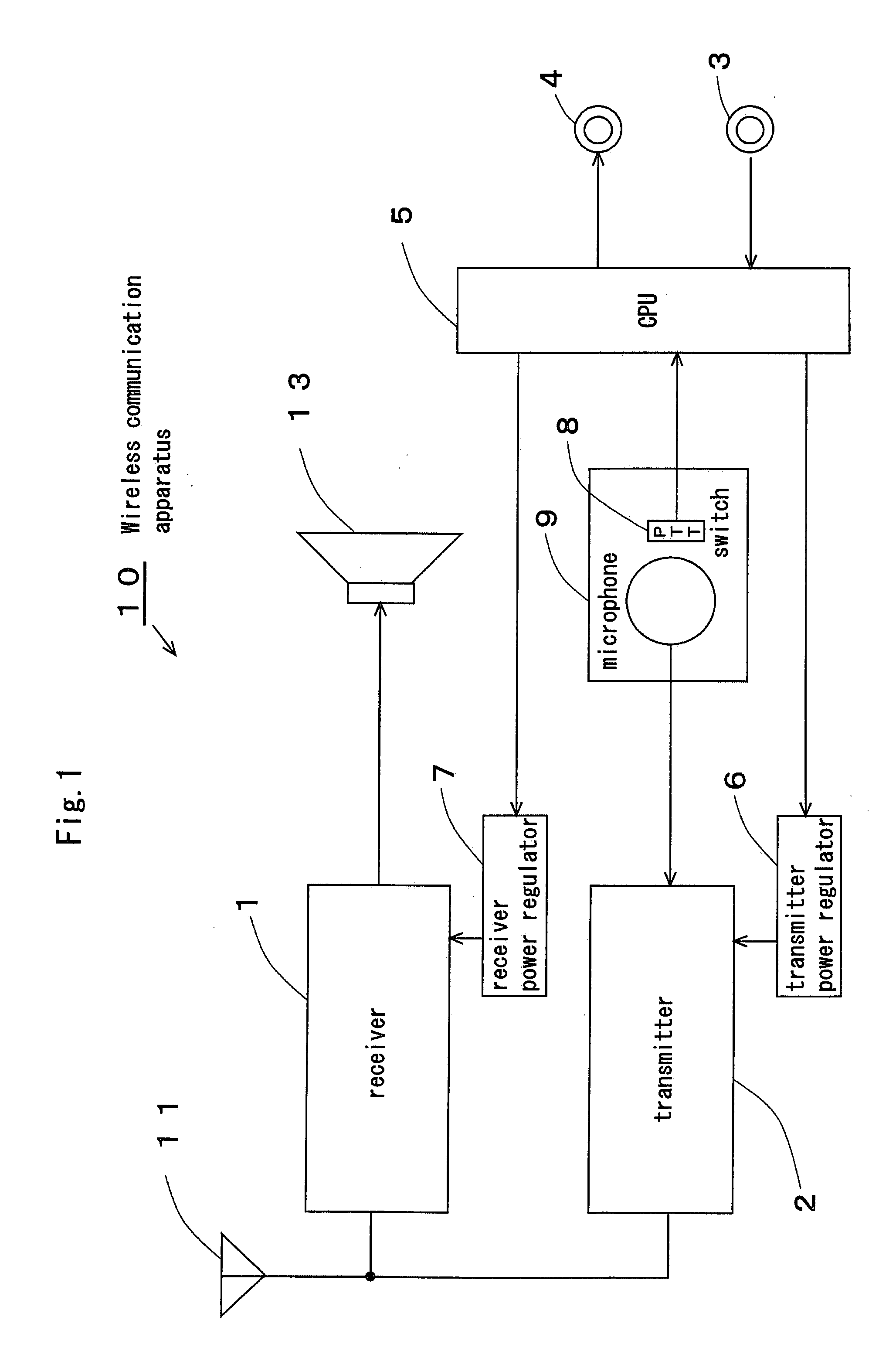
[0034]Described below are examples in which a plurality of wireless communication apparatuses according to the invention are set up so as to be adjacent to each other a short distance apart, and are connected together by a dedicated wire and used, such as when arranged, for example, in the same boat or the same building. In this case, these wireless communication apparatuses can be located separately at a distance or adjacently.

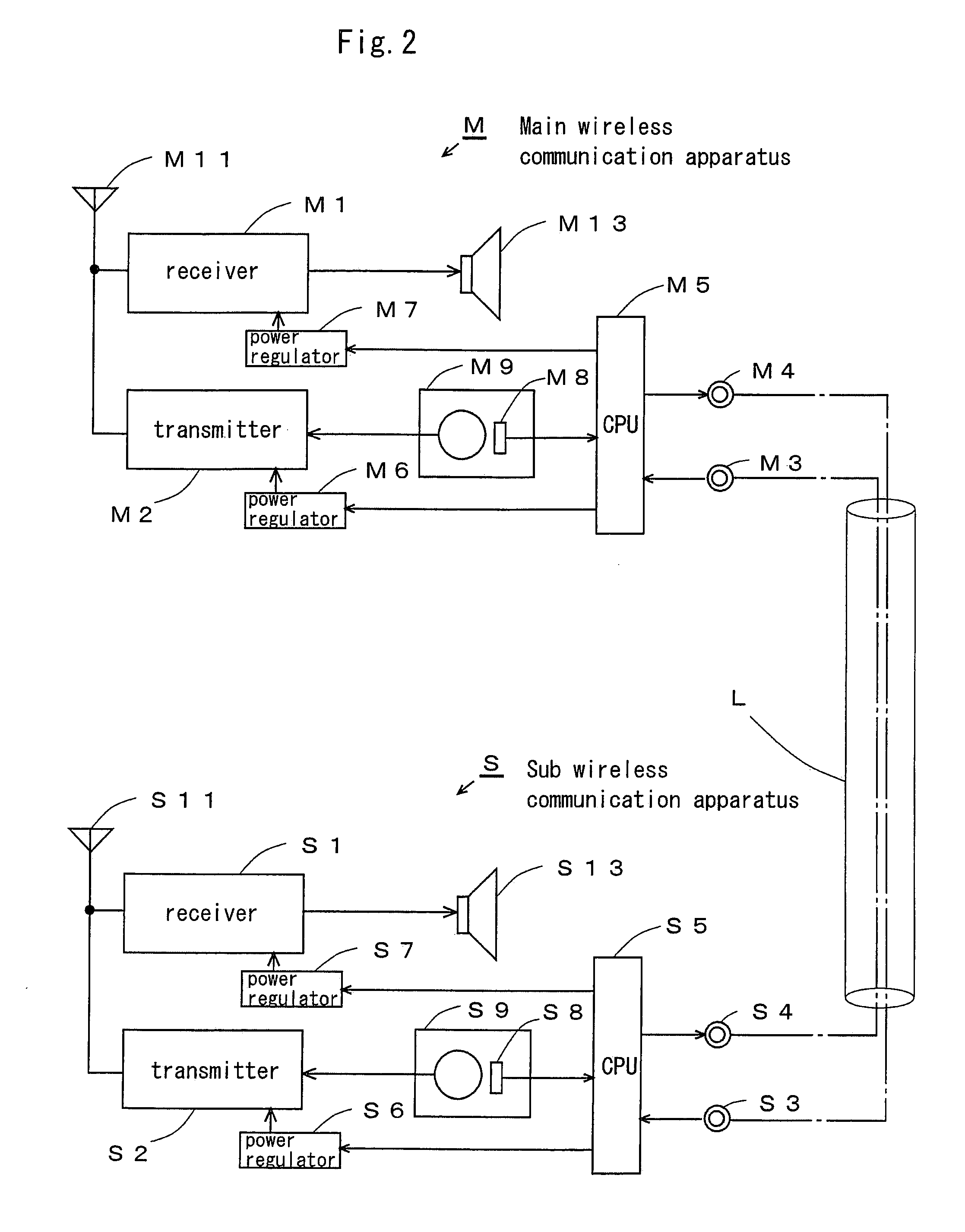
[0035]In the following description, M refers to a main currently used wireless communication apparatus which is any one of the located apparatuses, and the other standby wireless communication apparatuses are referred to as sub apparatuses S.

[0036]FIG. 2 illustrates a wireless communication system composed of a main wireless communication apparatus M for transmission and a sub apparatus S as a standby apparatus connected by a dedicated line L.

[0037]In the main wireless communication apparatus M of FIG. 2, the letter M is attached to the numbers used for compo...

example 2

[0059]The above description was of an example in which the power supply to the receiver 1 was stopped when reception limit signals are input from the outside, but, as signal attenuation means, for example, a high frequency attenuator 12 can be connected between the receiver 1 and receiving antenna 11, such as in the wireless communication apparatus 10B shown in FIG. 4. When a reception limit signal is input from the outside, in order to avoid damage to the receiver 1 and prevent transmitting inhibitory signals outside, the signal attenuation means 12 can be controlled by the CPU 5 to attenuate the signal incoming through the receiving antenna 11 to the receiver 1.

[0060]When, on the other hand, no reception limit signals are input from the outside, the signal attenuation means 12 is controlled by the CPU 5 so that the signals input from the receiving antenna 11 to the receiver 1 are not attenuated and are input to the receiver 1.

[0061]According to the present invention, when receptio...


PUM


Abstract

At least two or more wireless communication apparatuses (10) of the present invention are located adjacently or separately in a relatively confined area, wherein the output portion (4) of any one of currently used wireless communication apparatus of the wireless communication apparatuses (10) is connected to each input portions (3) of the other standby wireless communication apparatuses (10), while a radio signal being transmitted from the transmitter (2) of the currently used wireless communication apparatus (10), a reception limit signal is transmitted from the output portion (4) of said currently used apparatus to the respective input portions of the nearby standby apparatuses (10) so that the reception ability of the receiver (1) of said standby apparatus (10) is effectively limited.

Description

TECHNICAL FIELD OF THE INVENTION[0001]The present invention relates to a wireless communication apparatus, a wireless communication system employing a plurality of such wireless communication apparatuses that is employed in a wireless communication system wherein other wireless communication apparatuses are used as standby apparatuses during the operation of any one of currently used wireless communication apparatus of those apparatuses, and a method for controlling a plurality of the same apparatuses.BACKGROUND OF THE INVENTION[0002]As a precaution against malfunctions, boats and ships or the like which use wireless communication apparatuses are equipped, for example, with two wireless communication apparatuses, both are turned on, one predetermined unit of which is used as the main wireless communication apparatus, and the other is held in reserve as a standby unit.[0003]Under these circumstances, the signals transmitted from the one main wireless communication apparatus are recei...

Claims


Application Information

Patent Timeline
Patent Type & Authority Applications(United States)
IPC IPC(8): H04B1/44H04B1/3822H04B1/40H04B1/74H04B17/00H04W8/22H04W24/00H04W24/04H04W92/18
CPCH04B1/109
Inventor KITA, HITOSHI
Owner ICOM INC
Why Eureka
Try Eureka