
Implant Inserted Without Bone Anchors For Treatment of Urge Incontinence

a technology of incontinence and implants, which is applied in the field of incontinence implants inserted without bone anchors, to achieve the effect of reducing urge symptoms and effective reducing urge symptoms

Inactive Publication Date: 2009-04-30
AMS RES CORP
View PDF1 Cites 34 Cited by
  • Summary
  • Abstract
  • Description
  • Claims
  • Application Information

AI Technical Summary

Benefits of technology

[0026]The present invention recognizes that, when disturbed by an implantable material, the retropubic space will generate tough fibrous tissue, providing substantial holding power for an implant placed in that space. This body reaction can be exploited to help restore continence.
[0027]The present invention recognizes that an implantable article (e.g. a dynamic sling or hemi-sling) may be anchored to structure in the retropubic space, without the need of bone anchors and without the need to suture the implant to Cooper's ligament, the pubic bone or the tough rectus fascia. With the present invention, the implant may be anchored in the retropubic space (e.g. to endopelvic fascia) without the need to extend upward into the abdominus or rectus fascia. This avoids complications associated with invasive abdominal incisions.
[0031]The present invention is directed to methods of placing implants, hemi-slings, dynamic slings or other articles for treating incontinence that do not require abdominal incisions, or bone anchors. The present invention recognizes that it is not necessary to anchor a sling or other implantable article directly in bone or in the tough abdominal (rectus) fascia. As a result, the present invention is less invasive than conventional procedures and exhibits less potential for experiencing the complications associated with bone anchoring procedures.
[0032]Since surgical tools for this procedure need not extend through the abdominal wall, the present invention reduces the risk that vulnerable tissue (such as the bladder) will be damaged by a surgical instrument. The implant is preferably inserted through a vaginal incision that is preferably as small as possible. Other surgical routes such as transurethral and transperineal are also within the scope of the present invention. The present invention is particularly suitable for use with concomitant procedures such as a sacral colpopexy or pelvic floor repair. The present invention also preferably does not preclude subsequent surgeries.
[0047]In both midurethral and bladder neck slings, the effects were much less pronounced. Therefore, it is expected that if design and implantation technique (and location of the sling) of the transobturator sling is optimized for urge patients, this simple mechanical device can be used to effectively reduce urge symptoms.

Problems solved by technology

With many types of incontinence, however, the intraurethral pressure during the stress event rises above the support structure's ability to close the urethra, resulting in leakage.

Method used


Image

  • Implant Inserted Without Bone Anchors For Treatment of Urge Incontinence
  • Implant Inserted Without Bone Anchors For Treatment of Urge Incontinence
  • Implant Inserted Without Bone Anchors For Treatment of Urge Incontinence

Examples


Embodiment Construction

[0089]The following description is meant to be illustrative only and not limiting. Other embodiments of this invention will be apparent to those of ordinary skill in the art in view of this description.

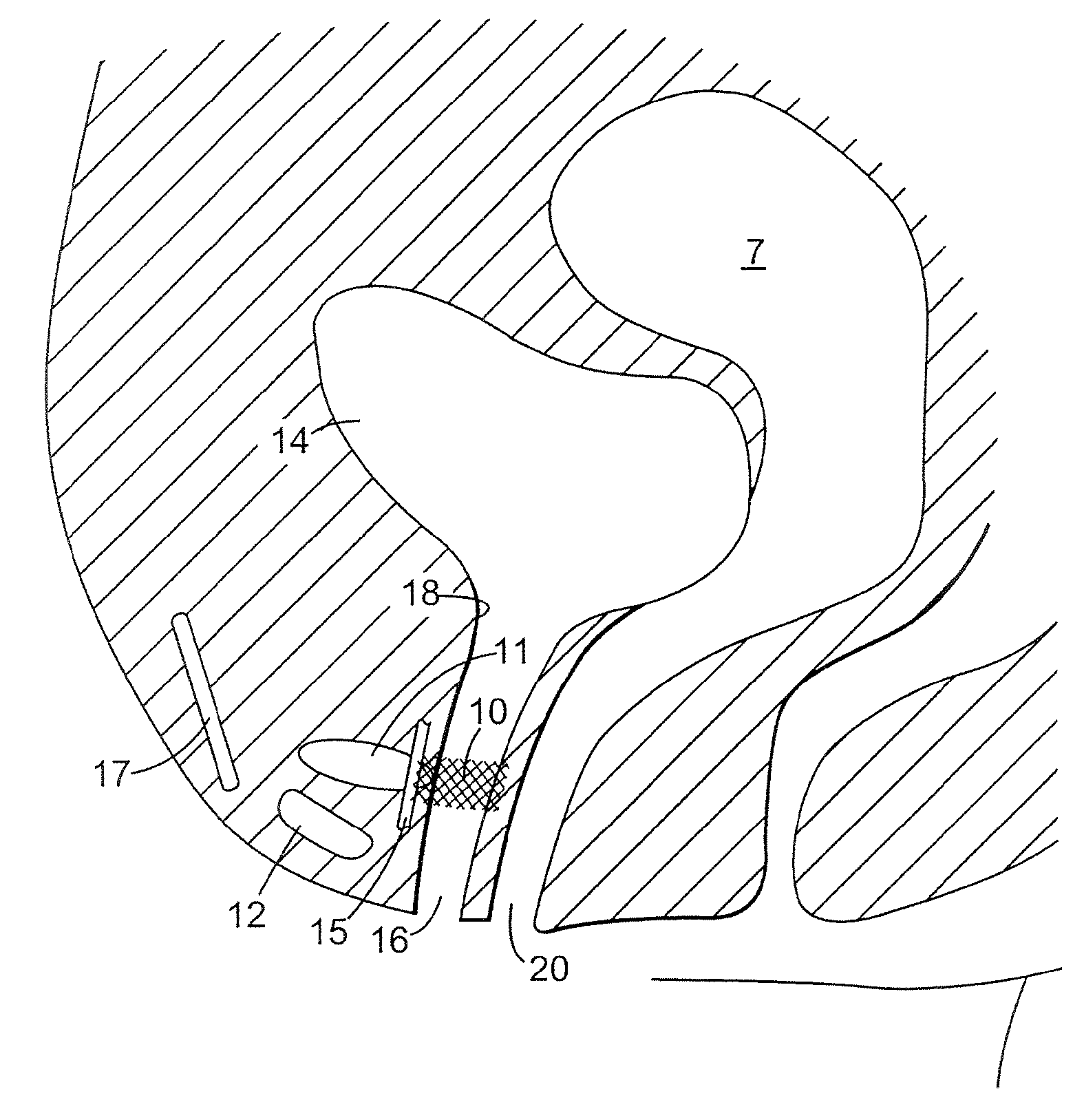
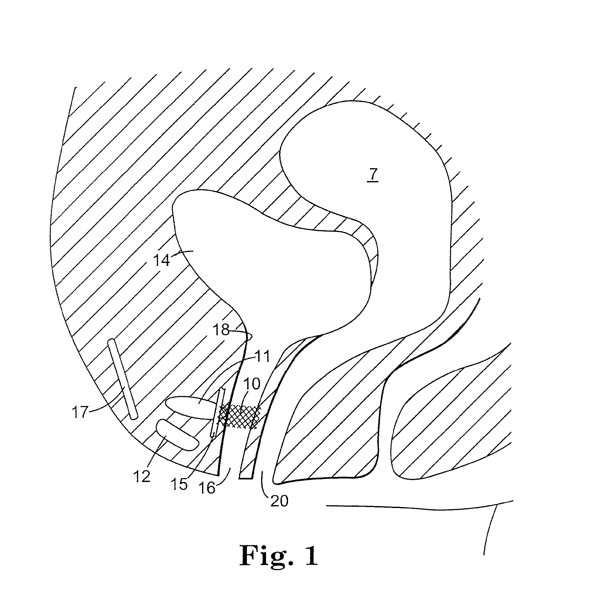
[0090]Referring to FIGS. 1 and 2, there is shown an implant 10 for treating incontinence in a patient. These figures schematically illustrate female anatomical features including the pubic bone 12, urethra 16, vagina 20, endopelvic fascia 15, a portion of the retropubic space 11, uterus 7, bladder 14, and rectus fascia 17. Notably, these structures are not shown to scale. For example, the retropubic space 11 is larger relative to other anatomical structures than the size depicted in FIG. 1.

[0091]The implant 10 comprises a thin, flexible structure that has a geometry, size and shape suitable for placement in the patient's retropubic space and for implantation in the retropubic space without bone anchors or suturing to Cooper's ligament or rectus fascia 17. In a preferred embodiment, th...


PUM


Abstract

The present invention discloses an implant for placement in the retropubic space of a patient. Novel methods and assemblies for use in conjunction with the implant are also described, which include mechanical positioning of the sling, placement of a mechanical implant underneath the urethra or mechanical vibration (intermittent) under the urethra or other incontinence lumen.

Description

CROSS REFERENCE TO RELATED APPLICATIONS[0001]The present application claims priority to U.S. Provisional Application Ser. No. 60 / 975,349 filed Sep. 26, 2007; and is a continuation-in-part of U.S. Utility application Ser. No. 11 / 264,071, filed Nov. 1, 2005, which is a divisional of U.S. Utility application Ser. No. 10 / 106,086 filed Mar. 25, 2002 and which claims the benefit of U.S. Provisional Application Ser. No. 60 / 279,794, filed Mar. 29, 2001; and U.S. Provisional Application Ser. No. 60 / 302,929, filed Jul. 3, 2001; and U.S. Provisional Application Ser. No. 60 / 307,836, filed Jul. 25, 2001, and U.S. Provisional Application Ser. No. 60 / 322,309, filed Sep. 14, 2001.BACKGROUND[0002]Loss of bladder control is a condition known as urinary incontinence. Millions of men and women of all ages suffer from this condition, which causes involuntary loss of urine. Although urinary incontinence may occur at any age, it is more common in women and in the elderly. Women may develop incontinence du...

Claims


Application Information

Patent Timeline
IPC IPC(8): A61F2/02A61B19/00
CPCA61B17/0401A61F2/0045A61B17/06109A61B2017/00495A61B2017/00805A61B2017/0409A61B2017/0412A61B2017/0414A61B2017/0417A61B2017/0435A61B2017/0437A61B2017/0438A61B2017/044A61B2017/0443A61B2017/0464A61B2019/306A61B17/0487A61B2090/036
Inventor LUND, ROBERT E.KOULLICK, EDOUARD A.OTTE, JOHN FRITZ
Owner AMS RES CORP
Learn More