Biopsy device with fluid delivery to tissue specimens

a biopsy device and tissue technology, applied in the field of tissue removal devices, can solve the problems that it is not always easy for physicians or other operating room personnel to separate or remove specimens from the devi

Active Publication Date: 2009-04-30
SENORX
View PDF99 Cites 68 Cited by
  • Summary
  • Abstract
  • Description
  • Claims
  • Application Information

AI Technical Summary

Benefits of technology

[0011]The tissue cutting member has an inner lumen preferably extending to a discharge port in the proximal end thereof for tissue specimen removal. While mechanical withdrawal of the tissue specimen may be employed, it is preferred to provide a vacuum within the cutting member from the proximal end of the cutting member (via the tissue collector interior) to aspirate the severed tissue specimen through the inner lumen of the cutting member to a tissue collection station. A higher fluid pressure may be maintained in the inner lumen of the cutting member distal to the tissue specimen to aid in transporting the specimen proximally through the inner lumen. In this manner, the mechanical withdrawal and / or the vacuum on the proximal end of the specimen and a higher pressure on the distal end of the specimen can move the specimen through the inner lumen of the cutting member to the tissue collector station.

Problems solved by technology

A variety of tissue collecting components have been proposed for biopsy devices but they have not always been easy for the physician or other operating room personnel to separate or remove the specimen from the device.

Method used


Image

  • Biopsy device with fluid delivery to tissue specimens
  • Biopsy device with fluid delivery to tissue specimens
  • Biopsy device with fluid delivery to tissue specimens

Examples


Embodiment Construction

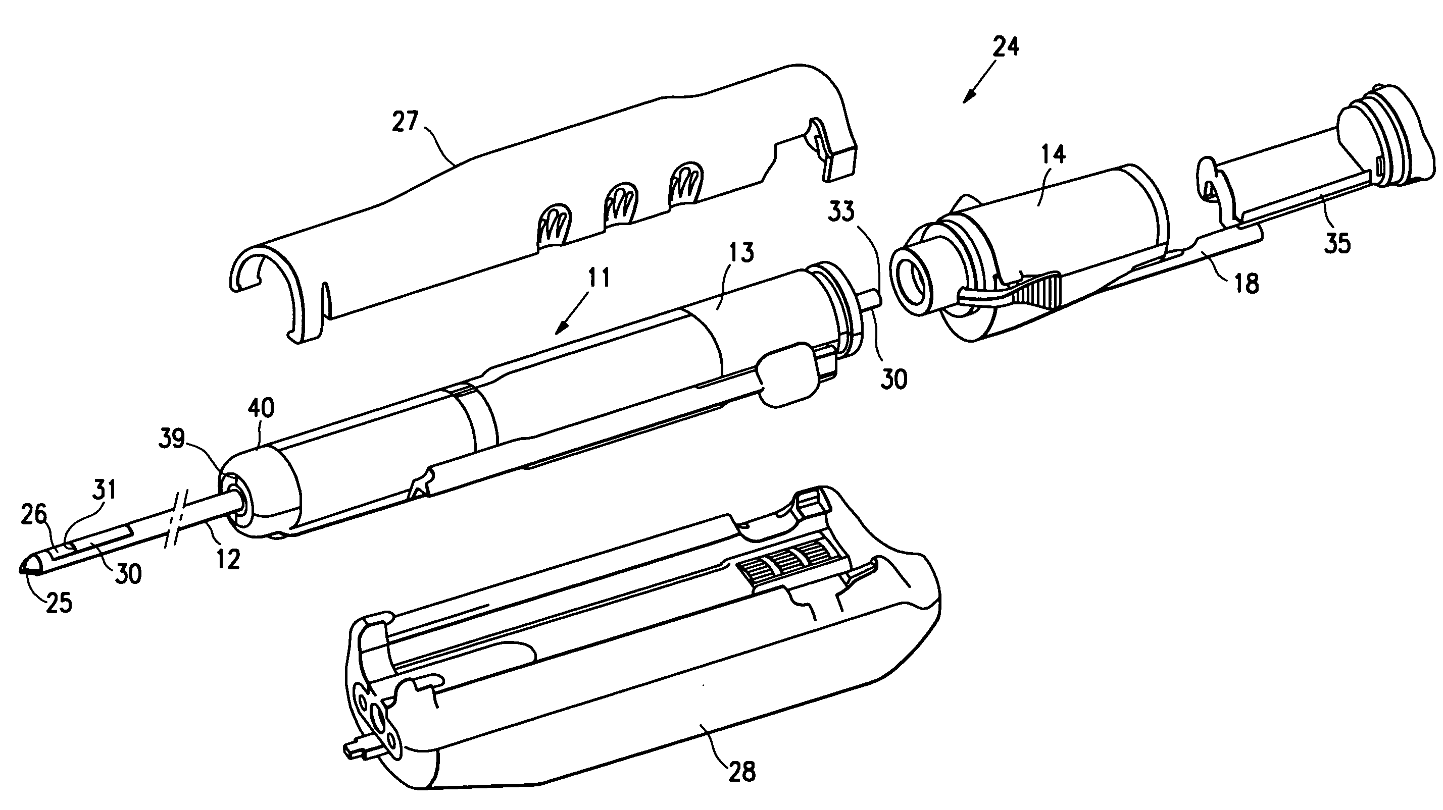
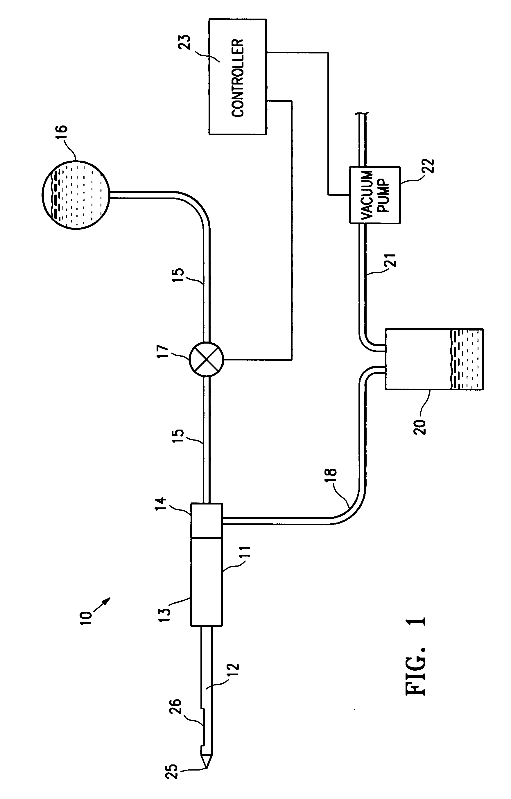
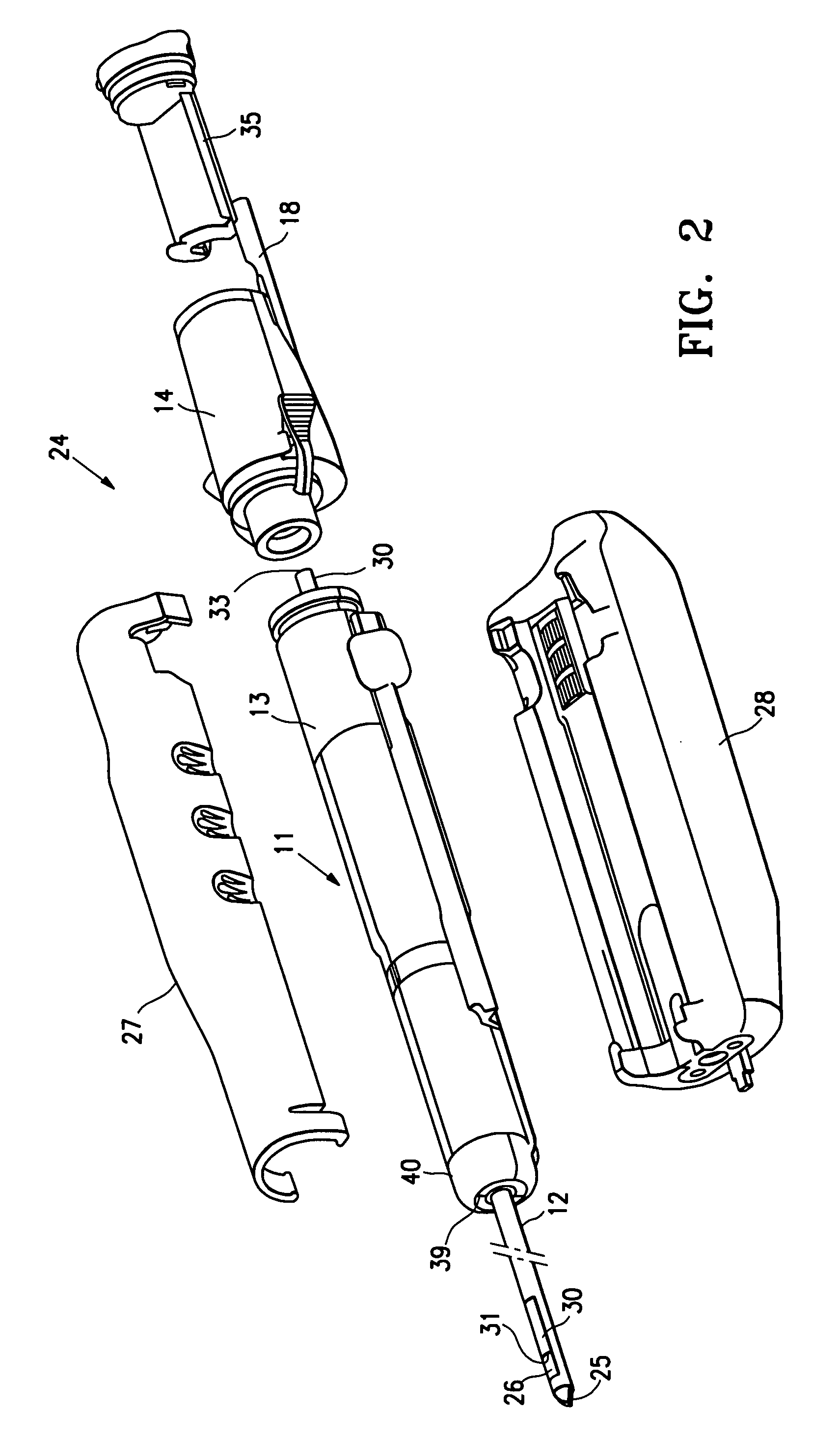
[0034]FIG. 1 schematically illustrates a biopsy system 10 embodying features of the invention. The system 10 includes a probe component 11 with an elongated tubular section 12, a proximal housing 13 and a tissue specimen collector 14 attached to the proximal housing. A first conduit 15 extends from fluid source 16 to the proximal end of the tissue collector 14 to deliver fluid to tissue specimens in the interior of the collector. A valve 17 is provided to control the fluid flow through the first conduit 15. A second conduit 18 extends to the tissue specimen collector 14 for application of a vacuum to the interior of the tissue specimen collector to aspirate fluid applied to one or more severed tissue specimens within the specimen collector. The second conduit 18 directs the aspirated fluid and debris to waste container 20. A third conduit 21 extends from the waste container 20 to a vacuum pump 22 which provides vacuum to the waste container and ultimately to the interior of the tiss...


PUM

PropertyMeasurementUnit
vacuumaaaaaaaaaa
level of vacuumaaaaaaaaaa
pressureaaaaaaaaaa

Abstract

The invention is directed to a system and method for separating and collecting one or more tissue specimens from a target site within a patient and flushing the specimen to remove blood, debris and the like before the specimen is removed from the biopsy device. The flow of flushing fluid to the tissue collector is preferably controlled to coincide with delivery of one or more specimens to the collecting tray or basket of the device or after the receipt of the specimen within the tissue collector to ensure that the fluid is applied to a fresh specimen. The tissue tray or basket within the tissue collector has an open or foraminous portion to facilitate removal of fluid, such as the applied fluid and blood, and other debris from the tissue specimens on the tray. Vacuum is provided within the tissue collector, preferably under the tray to remove fluid and debris from the collector interior.

Description

RELATED APPLICATIONS[0001]This application is a continuation-in-part of application Ser. No. 11 / 197,827 filed Aug. 5, 2005 which is incorporated herein in its entirety by reference.FIELD OF THE INVENTION[0002]The present invention relates generally to tissue removing devices such as biopsy devices and the methods of using such devices. More specifically, it is directed to an improved biopsy or other tissue removing device and method of using the device which includes flushing one or more specimens with suitable fluid within a tissue collector to remove blood, debris and the like from the specimen(s).BACKGROUND OF THE INVENTION[0003]In diagnosing and treating certain medical conditions, such as potentially cancerous tumors, it is usually desirable to perform a biopsy, in which a specimen of the suspicious tissue is removed for pathological examination and analysis. In many instances, the suspicious tissue is located in a subcutaneous site, such as inside a human breast. To minimize s...

Claims


Application Information

Patent Timeline
Patent Type & Authority Applications(United States)
IPC IPC(8): A61B10/02
CPCA61B10/0275A61B10/0283A61B2010/0208A61B2010/0225A61M1/0056A61B10/0266A61B2217/005A61M1/79B01D2221/10B01D29/31
Inventor QUICK, JR., RICHARD L.SHABAZ, MARTIN V.LOUW, FRANK R.LUBOCK, PAULSAFABASH, JASON H.
Owner SENORX
Why Eureka
Try Eureka