Tissue modification devices

a tissue modification and flexible technology, applied in the field of medical/surgical devices and methods, can solve the problems of difficult to modify certain tissues to achieve a desired effect, more technical challenges, and particularly challenging, and achieve the effect of not inhibiting the flexing or bending (flexibility) of the elongated body

Active Publication Date: 2012-03-15
MIS IP HLDG LLC +1
View PDF3 Cites 44 Cited by
  • Summary
  • Abstract
  • Description
  • Claims
  • Application Information

AI Technical Summary

Benefits of technology

[0021]Any of the tissue modification devices described herein may include one or more guidewire couplers at the distal end of the device. A guidewire coupler typically engages with a portion (e.g., the proximal end) of the guidewire to secure the guidewire to the guidewire coupler. The guidewire coupler may be configured so that a portion of the guidewire (such as the proximal end of the guidewire) is held securely in the distally located guidewire coupler. The guidewire coupler may releasably hold the guidewire in position. The guidewire is typically held by the guidewire coupler so that when engaged, the guidewire and the guidewire coupler do not move relative to each other. Additionally, the guidewire may be typically held so that pulling on the distal end region of the guidewire results in pulling the device from its distal end, i.e. pulling the device from where the guidewire is coupled via the guidewire coupler. Thus, the coupler may engage the guidewire with sufficient strength and stability to allow the device to be positioned within the body by drawing on the distal end of the guidewire.
[0025]One or more cutting edges may be included on each rung. The cutting edge may be part of a blade. In some variations of the tissue modification devices, the cutting edge(s) on the rung or rungs project from the surface of the rung. For example, a blade may be formed by a portion of the rung that extends up (e.g., out of the plane of the tissue modification device). The blade or cutting edge may be oriented so that it optimally cuts tissue as the device is urged against the target tissue. For example, the blade may be oriented so the blade is perpendicular to the long axis (the length) of the device. The blade may be shaped (e.g., flat, pointed, or the like). The shape and orientation of the blade may help steer the device as it is urged against the tissue.
[0027]The cutting edges on adjacent rungs of the tissue modification device may be axially offset from each other. Offsetting the axial position of the blades (or cutting edges) may enhance cutting by presenting a wider effective cutting surface. Thus, relatively narrow (or pointed) blades / cutting edges may be used to cut a region of tissue that is wider than the blade / cutting surface width.
[0029]In some variations the tissue modification devices may include blades of different shapes and sizes on the same device. Blades may have different heights (e.g., projecting from the rung), widths, shapes, etc. Different shaped / sized blades may also be arranged along the length of the tissue modification device (e.g., along the tissue modification surface or side of the device). For example, in some variations, blades at the more proximal end of the tissue modification device may be more closely spaced and may have a lower profile than blades more distally. Alternatively, the blades near the ends (e.g. proximal and distal ends) of the tissue modification region of the device may be less closely spaced and have a slightly higher profile than blades along the center of the length of the device. These arrangements may help overcome stiction when using the device to modify tissue. For example, the tissue modification device could have blades with graduated profiles so that the blades near the ends (proximal and distal) permit a “running start” for the tissue modification from the larger blades. In some variations, the profile of the blades near one or both ends (e.g., the distal end) have a lower profile than blades near the middle of the tissue modification device
[0042]The posterior substrate may be secured in parallel to the anterior (tissue cutting) surface. In some variations, the posterior substrate is a relatively rigid elongate substrate extending at least partially proximally and partially distally. The posterior substrate may extend the same distance as the anterior surface, so that the tissue collection region underlies all of the cutting edges. In some variations, the posterior substrate is formed so that it does not inhibit the flexing or bending (the flexibility) of the elongate body. In some variations, the posterior substrate is formed of an expandable material that allows the posterior substrate to expand as the tissue collection region is filled.

Problems solved by technology

Minimally invasive (or “less invasive”) surgical procedures often involve modifying tissue through one or more small incisions or percutaneous access, and thus may be more technically challenging procedures.
Some of the challenges of minimally invasive tissue modification procedures include working in a smaller operating field, working with smaller devices, and trying to operate with reduced or even no direct visualization of the tissue for tissues) being modified.
For example, using arthroscopic surgical techniques for repairing joints such as the knee or the shoulder, it may be quite challenging to modify certain tissues to achieve a desired result, due to the required small size of arthroscopic instruments, the confined surgical space of the joint, lack of direct visualization of the surgical space, and the like.
It may be particularly challenging in some surgical procedures, for example, to cut or contour bone or ligamentous tissue with currently available minimally invasive tools and techniques.
For example, trying to shave a thin slice of bone off a curved bony surface, using a small-diameter tool in a confined space with little or no ability to see the surface being cut, as may be required in some procedures, may be incredibly challenging or even impossible using currently available devices.
The most common form of spinal stenosis occurs in the lower (or lumbar) spine and can cause severe pain, numbness and / or loss function in the lower back and / or one or both lower limb.
Impingement of neural and / or neurovascular tissue in the spine by one or more of these tissues may cause pain, numbness and / or loss of strength or mobility in one or both of a patient's lower limbs and / or of the patient's back.
When these conservative treatment options fail and symptoms are severe, as is frequently the case, surgery may be required to remove impinging tissue and decompress the impinged nerve tissue.
Removal of vertebral bone, as occurs in laminectomy and facetectomy, often leaves the affected area of the spine very unstable, leading to a need for an additional highly invasive fusion procedure that puts extra demands on the patient's vertebrae and limits the patient's ability to move.
Unfortunately, a surgical spine fusion results in a loss of ability to move the fused section of the back, diminishing the patient's range of motion and causing stress on the discs and facet joints of adjacent vertebral segments.
Such stress on adjacent vertebrae often leads to further dysfunction of the spine, back pain, lower leg weakness or pain, and / or other symptoms.
Furthermore, using current surgical techniques, gaining sufficient access to the spine to perform a laminectomy, facetectomy and spinal fusion requires dissecting through a wide incision on the back and typically causes extensive muscle damage, leading to significant post-operative pain and lengthy rehabilitation.
Thus, while laminectomy, facetectomy, and spinal fusion frequently improve symptoms of neural and neurovascular impingement in the short term, these procedures are highly invasive, diminish spinal function, drastically disrupt normal anatomy, and increase long-term morbidity above levels seen in untreated patients.

Method used


Image

  • Tissue modification devices
  • Tissue modification devices
  • Tissue modification devices

Examples


Embodiment Construction

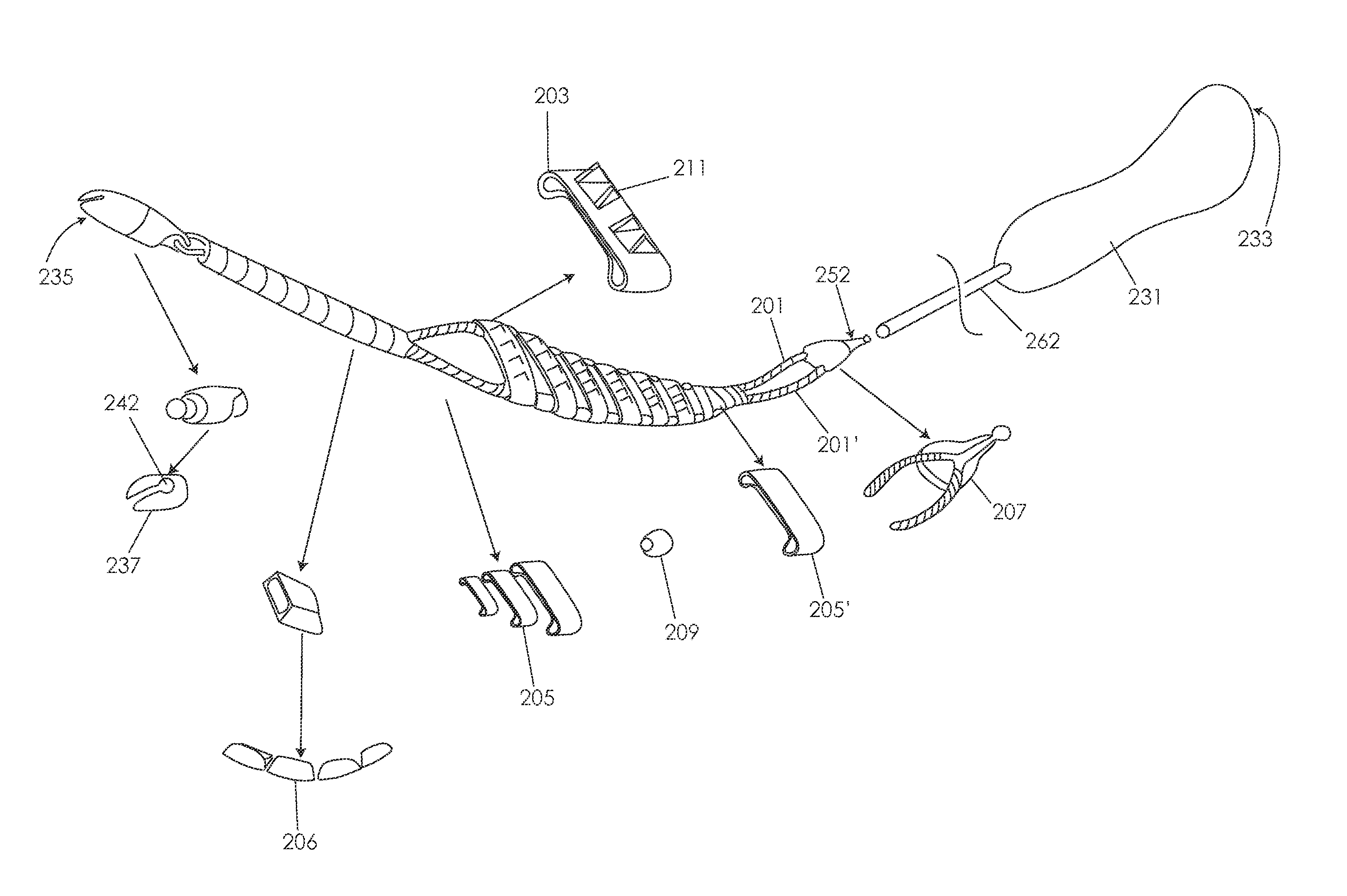
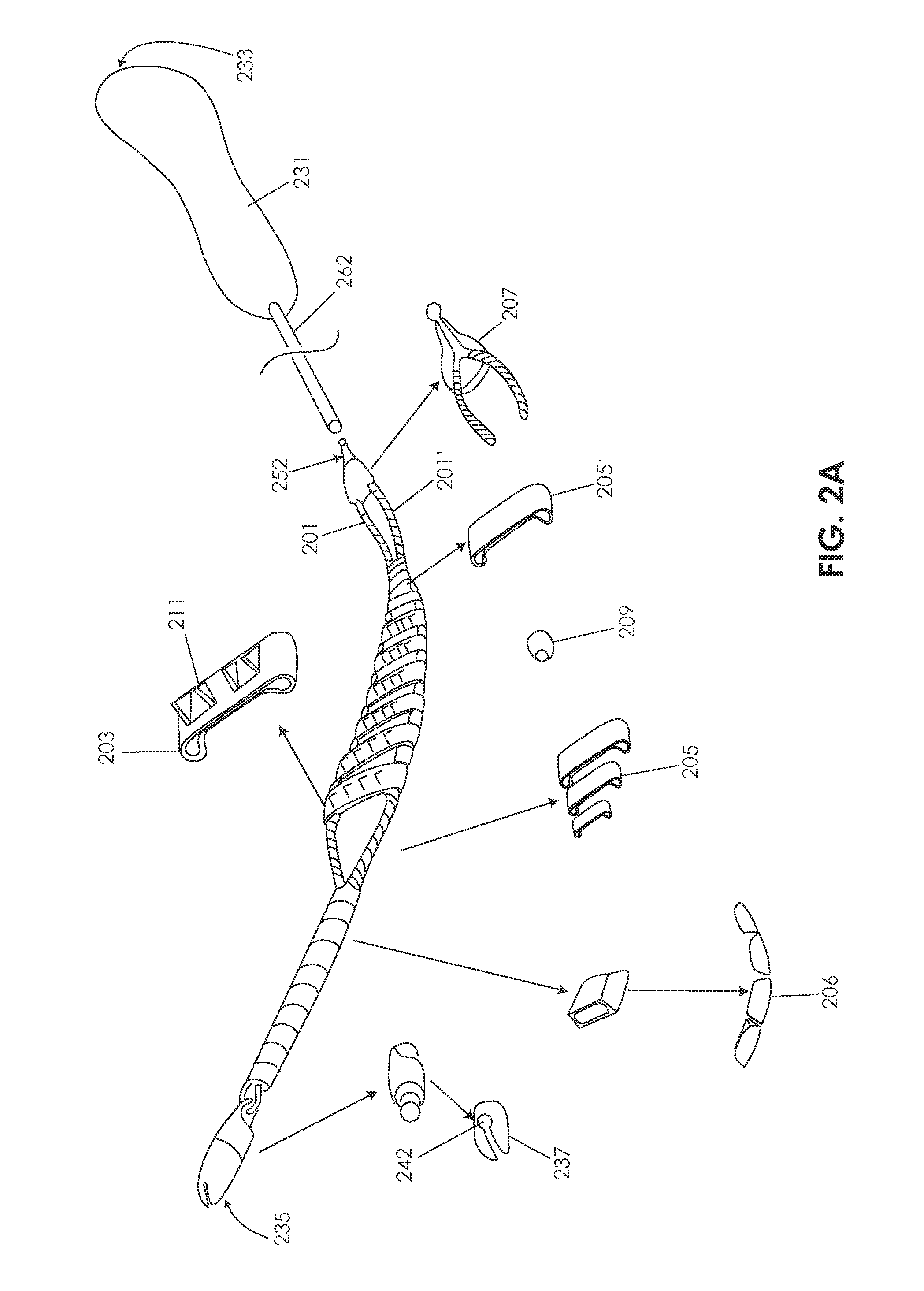
[0105]Various embodiments of tissue modification devices and systems, as well as methods for making and using tissue modification devices and systems, are provided herein. In general, a flexible tissue-modification device as described herein is configured to remove tissue from a patient. In particular, these tissue-modification devices may be configured to decompress spinal stenosis. These devices typically include a flexible elongate body that extends proximally to distally (proximal / distal), and is configured to be inserted into a patient so that it extends around the target tissue, so that it can be bimanually pulled against the target tissue by applying tension to either end of the device. Thus, the device may be extended into, through, and / or around a spinal foramen. The device is flexible in at least one plane. For example, in variations in which the device has an elongated ribbon shape that is long and flat with a width greater than the thickness, the device includes a first ...


PUM


Abstract

Described herein are elongate devices for modifying tissue having a plurality of flexibly connected rungs or links, and methods of using them, including methods of using them to decompress stenotic spinal tissue. These devices may be included as part of a system for modifying tissue. In general, these devices include a plurality of blades positioned on (or formed from) rungs that are flexibly connected. The rungs are typically rigid, somewhat flat and wider than they are long (e.g., rectangular). The rungs may be arranged, ladder like, and may be connected by a flexible connector substrate or between two or more cables. Different sized rungs may be used. The blades (on the rungs) may be arranged in a staggered arrangement. A tissue-collection or tissue capture element may be used to collect the cut or modified tissue.

Description

CROSS-REFERENCE TO RELATED APPLICATIONS[0001]This patent application claims priority as divisional of U.S. patent application Ser. No. 12 / 324,147, filed on Nov. 26, 2008, titled “TISSUE MODIFICATION DEVICES”, which claims priority as a continuation-in-part of U.S. patent application Ser. No. 11 / 952,934, filed Dec. 7, 2007, titled “TISSUE REMOVAL DEVICES AND METHODS”. U.S. patent application Ser. No. 12 / 324,147 also claims priority to U.S. Provisional Patent Application Ser. No. 61 / 080,647, filed Jul. 14, 2008, and U.S. Provisional Patent Application Ser. No. 61 / 081,685, filed Jul. 17, 2008. These applications are herein incorporated by reference in their entirety.INCORPORATION BY REFERENCE[0002]All publications and patent applications mentioned in this specification are herein incorporated by reference in their entirety as if each individual publication or patent application was specifically and individually indicated to be incorporated by reference.FIELD OF THE INVENTION[0003]The p...

Claims


Application Information

Patent Timeline
Patent Type & Authority Applications(United States)
IPC IPC(8): A61B17/16
CPCA61B17/14A61B17/1659A61B17/1671A61B17/320016A61B17/32002A61B2017/143A61B2017/00261A61B2017/145A61B2017/320004A61B2017/320008A61B2017/32006A61B17/3207A61B17/149A61B17/1631A61B17/1735
Inventor SCHMITZ, GREGORY P.WALLACE, MICHAEL P.LEGUIDLEGUID, RONALDCANTORNA, NESTOR C.SHAPIRO, JAMESBLEICH, JEFFERY L.
Owner MIS IP HLDG LLC
Why Eureka
Try Eureka