
Devices and methods for applying compression socks to feet

Inactive Publication Date: 2021-08-05
SOMMER PAUL G
View PDF0 Cites 0 Cited by
  • Summary
  • Abstract
  • Description
  • Claims
  • Application Information

AI Technical Summary

Benefits of technology

The invention relates to a device and method for applying a compression sock to a user's foot and leg for treatment or prevention of medical conditions. The device is designed to be easy to use and requires minimal physical strength from the user. The method involves placing the compression sock in the device and expanding the opening of the device to fit the user's foot, then sliding the user's leg into the device and applying the compression sock. This invention reduces the need for physical strength and coordination required for previous devices, making it more comfortable and easier to use for users.

Problems solved by technology

Lower extremity conditions such as leg edema, venous insufficiency, varicose veins, cellulitis, and deep venous thrombosis affect millions of people and cost billions of dollars in health care expenditures and insurance costs.
Currently, the leading cause of insufficient treatment of these conditions is the lack of compliance in patients' use of prescribed compression socks (also referred to as compression stockings or hoses) due at least in part to the manual difficulty in putting on the socks, into which an individual must typically force their entire lower leg against the resistance of the compression forces generated by the sock.
Often, patients simply do not have the finger, hand, or arm strength and / or lack sufficient flexibility and coordination with which to put on compression socks.
Due to this lack of compliance, people may retain fluid edema within their legs, leading to excessive pressure against the skin, dermal capillaries, and subcutaneous circulation potentially leading to a breakdown of skin and subcutaneous tissue.
However, these devices are often difficult to coordinate and use.
Very often the types of individuals who need compression socks, such as the elderly, often do not have the hand and grip strength required to pull this rope or the coordination of two hands in which to do this.
During use, these devices are also prone to slipping out from under the sock and therefore need to be reapplied.
This approach is not entirely effective because adequate material tension required of a compression material results in the zipper being difficult to operate, especially since the user can only use two fingers to grasp and pull the zipper, and the user is often not strong enough to pull the zipper against the compressive strength of the material.
The zipper itself is unattractive, which can further contribute to noncompliance of use.
Significant problems with this approach are that users may not be able to bind the sock to apply adequate pressure, and the pressure may not be evenly dispersed relative to what can be achieved with a conventional compression sock.
If the compression tension is tighter proximally than it is distally, the compression may create an adverse tourniquet effect.
This does not eliminate the need for finger strength, coordination, and manipulation (dexterity) to apply the sock, and can complicate the procedure due to there being less tactile sense due to the rubber gloves.
This approach also does not eliminate the need for finger strength, coordination, and manipulation, and has the added drawback of significantly increasing the tightness of the foot portion of the sock, which is often the most difficult part of the sock to put on when using the fingers.

Method used


Image

  • Devices and methods for applying compression socks to feet
  • Devices and methods for applying compression socks to feet
  • Devices and methods for applying compression socks to feet

Examples


second embodiment

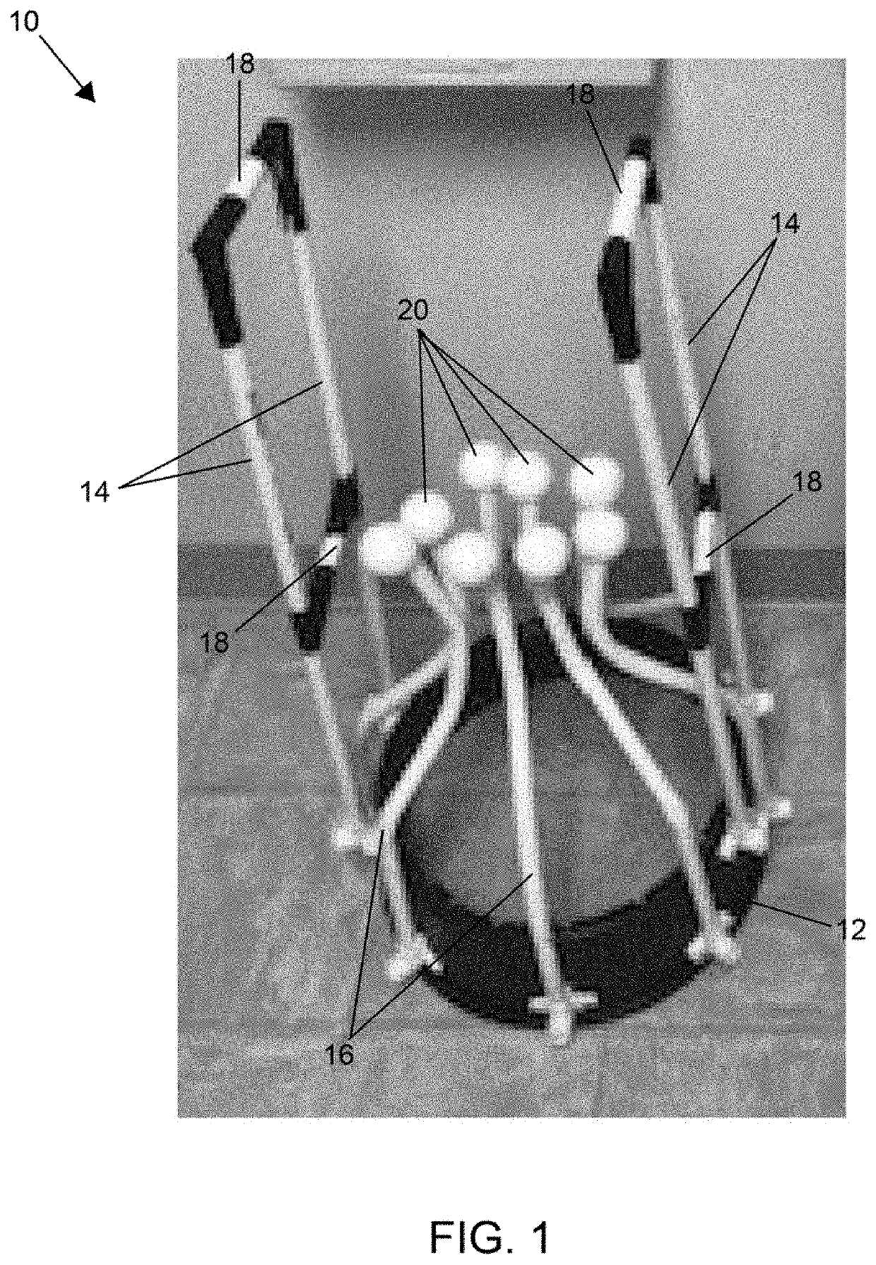
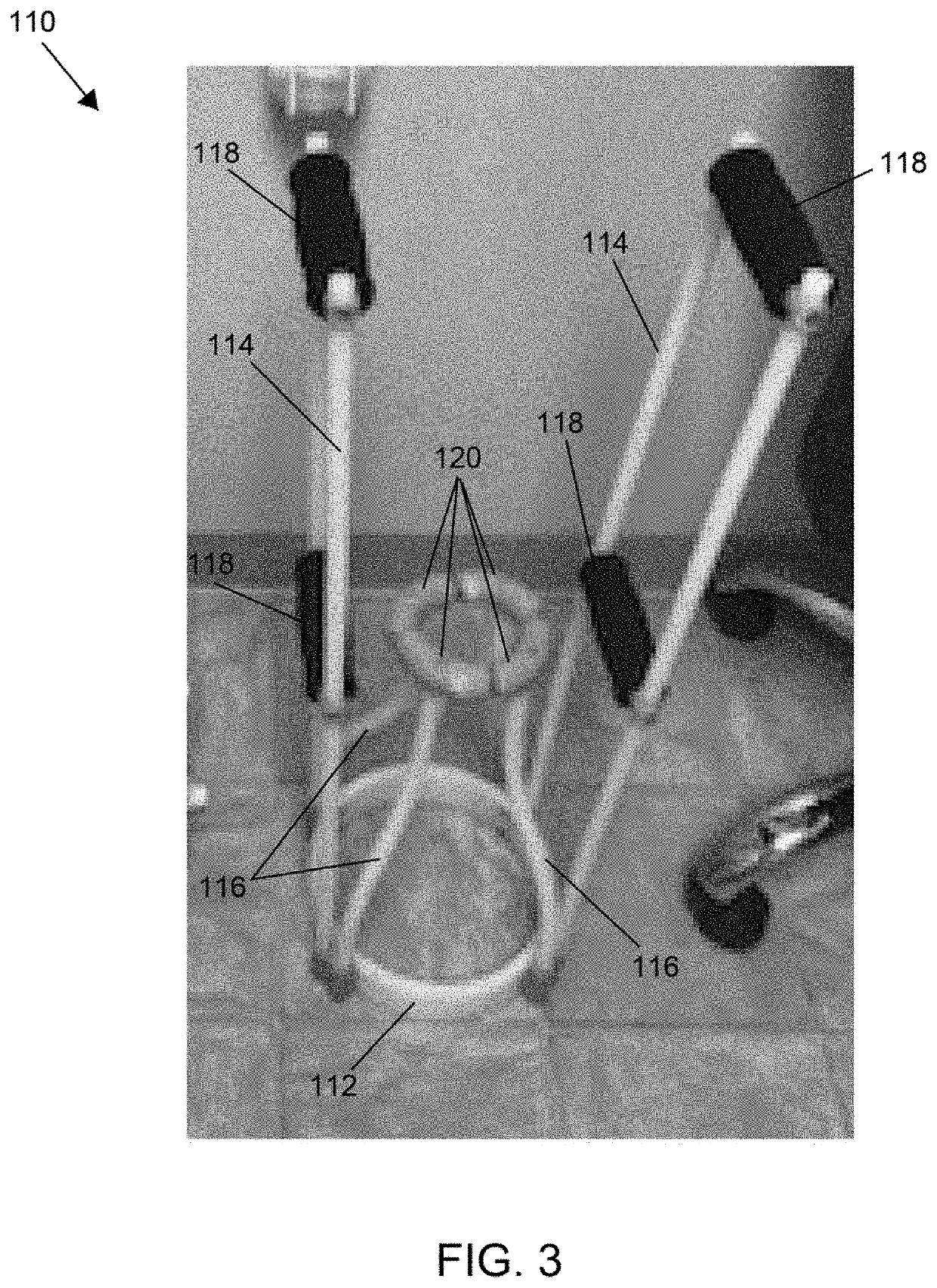
[0029]FIGS. 3 and 4 depict a device 110 which replaces the spherical distal ends 20 of FIGS. 1 and 2 with soft flexible serrated members 120 that have an arcuate shape so that, together, the soft flexible members 120 define a generally circular opening at the entrance to the arms 116. Each of the soft flexible members 120 are mounted to an individual arm 116. Under certain circumstances, the soft flexible members 120 at the distal ends of the arms 116 may promote the ease with which a compression stocking can be installed on the device110.

third embodiment

[0030]FIGS. 5, 10, and 11 depict a device 210 which replaces the spherical distal ends 20 of FIGS. 1 and 2 and the soft flexible serrated members 120 of FIGS. 3 and 4 with rollers 220. Each roller 220 is connected to the distal ends of two adjacent arms 216 such that the device 210 comprises eight arms 216 and four rollers 220 that define a generally square-shaped opening at the distal ends of the arms 216 rather than the circular-shaped opening of the embodiment of FIGS. 1 through 4. The axial ends of each roller 220 may be rounded to eliminate sharp corners. The rollers 220 are preferably capable of freely rotating to further decrease the active friction between the distal ends of the arms 216 and the compression sock as it is being applied. The two arm connections to each of the rollers 220 can also provide greater stability during use while also permitting a desirable degree of lateral or outward flexible motion of the arms 216 in order for the arms 216 to expand and allow passa...


PUM


Abstract

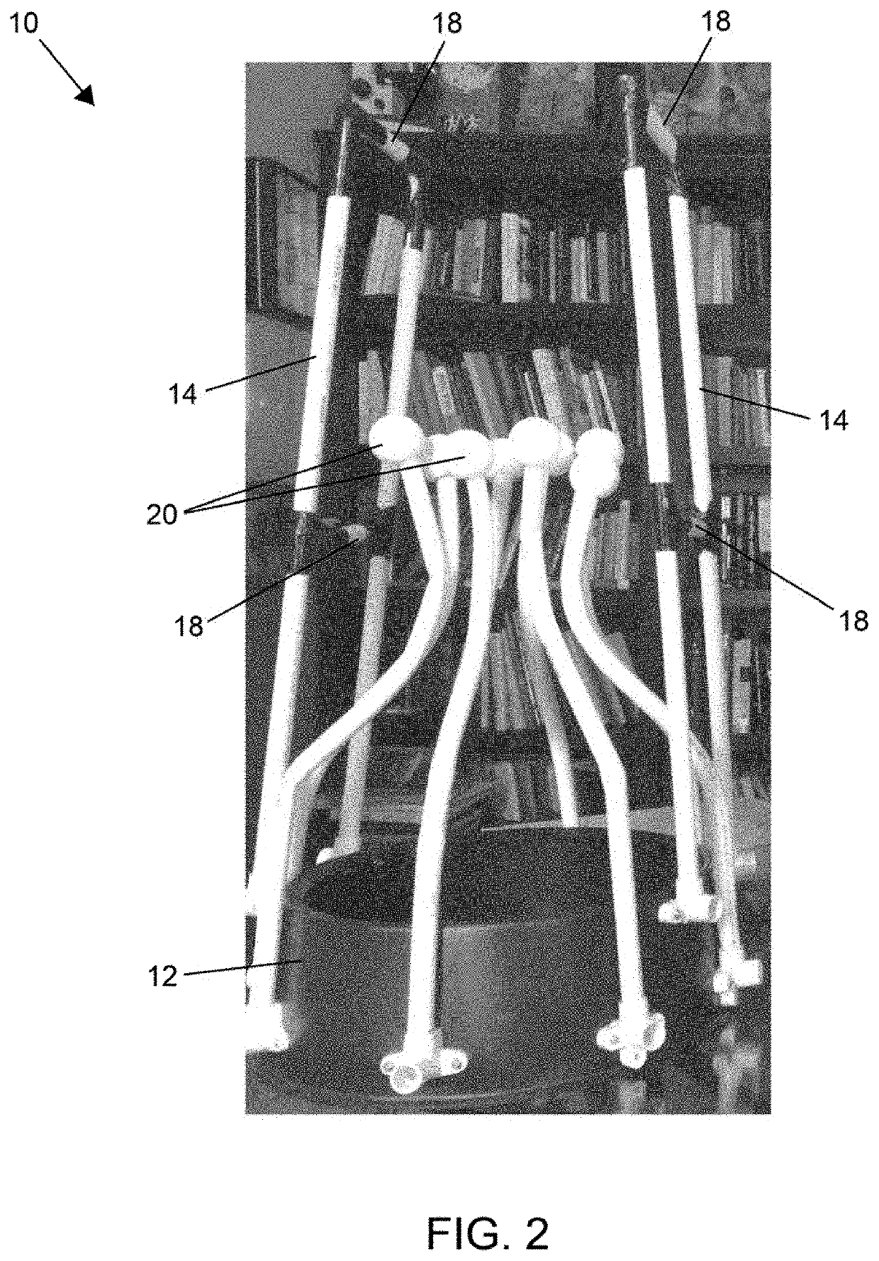
Devices and methods for assisting a user to don and remove a compression sock from the user's leg. The device includes a base, at least two side members secured to the base on opposite sides thereof, and multiple arms extending from the base in a direction along the longitudinal axis and between the side members. Each of the arms has a midpoint that curves inward toward the longitudinal axis of the device, and terminates at a distal end. The arms in combination form a composite shape that has a midportion that curves inward toward a longitudinal axis of the device to define a neck, defines an interior that is surrounded by the midportions of the arms and within which the longitudinal axis of the device is disposed, and defines an opening surrounded by the distal ends of the arms.

Description

CROSS REFERENCE TO RELATED APPLICATIONS[0001]This application claims the benefit of U.S. Provisional Application Nos. 62 / 969,959 filed Feb. 4, 2020, 63 / 017,723 filed Apr. 30, 2020, and 63 / 106,709 filed Oct. 28, 2020. The contents of these patent documents are incorporated herein by reference.BACKGROUND OF THE INVENTION[0002]The present invention generally relates to compression socks, stockings, sleeves, etc. (collectively, referred to herein as socks) and their use. The invention particularly relates to systems and methods suitable for aiding users in applying medical grade high pressure or low pressure compression socks to their feet and legs.[0003]Lower extremity conditions such as leg edema, venous insufficiency, varicose veins, cellulitis, and deep venous thrombosis affect millions of people and cost billions of dollars in health care expenditures and insurance costs. Currently, the leading cause of insufficient treatment of these conditions is the lack of compliance in patient...

Claims


Application Information

Patent Timeline
IPC IPC(8): A47G25/90A61F13/08
CPCA47G25/905A41B2400/44A61F13/08A61F15/005
Inventor SOMMER, PAUL G.
Owner SOMMER PAUL G
Learn More