
Three-dimensional object and manufacturing method thereof

a manufacturing method and three-dimensional object technology, applied in the direction of additive manufacturing processes, manufacturing tools, additive manufacturing with solid and fluid, etc., can solve the problems of product breakage and product quality reduction, and achieve the effect of improving attachment, avoiding tension building, and increasing flowability

Pending Publication Date: 2022-02-17
ADMATEC EURO
View PDF0 Cites 1 Cited by
  • Summary
  • Abstract
  • Description
  • Claims
  • Application Information

AI Technical Summary

Benefits of technology

The present invention provides a manufacturing process for producing a three-dimensional object using a resin that can be polymerized at a temperature above its glass temperature, which has advantages such as increased flowability, reduced tension, and improved attachment between layers. The process also increases the density of the layers and reduces delamination problems, resulting in a stronger final product. The cured resin acts as a sacrificial organic binder glue between particles in the object, which provides stability for further processing. Using a pre-heated slurry reduces moisture absorption, resulting in an improved slurry quality and reduced delamination issues. Sintering compacts and solidifies the brown body, resulting in a smaller and stronger object with increased density.

Problems solved by technology

Conventional methods may at times suffer from decreased product quality, e.g. in terms of delamination issues wherein the distinct layers separate during or after the manufacturing process, which leads to product break-down.

Method used


Image

  • Three-dimensional object and manufacturing method thereof

Examples


example

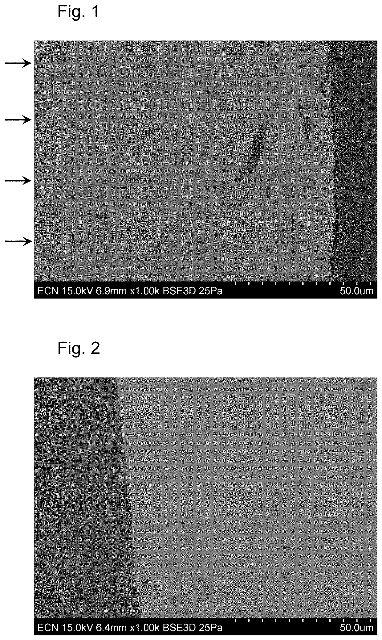
[0054]A radiation-curable slurry for additive manufacturing was made of 28 wt % of the polymerizable resin A (Tg=34° C.), comprising neopentyl glycol propoxylate (2 PO) diacrylate, 0.5 wt % of photoinitiator bis(2,4,6-trimethylbenzoyl)-phenylphosphineoxide (Irgacure ir819), 71.5 wt % of zirconium oxide (ZrO2) particles. A slurry was made using a high speed mixer and then heated to a temperature of 60° C. The printing was performed on an Admaflex printer at the same temperature, using radiation with a wavelength between 390 and 420 nm with a curing time of 2 s and a layer thickness of 20 μm. A control experiment was performed wherein the slurry was at room temperature (about 20° C.), and printing was performed at that same temperature. The bodies of both experiments were debinded and converted in air at a top temperature of 1000° C. Sintering occurred at a temperature of 1500° C. After sintering, a zirconium oxide body was obtained.

[0055]The resulting bodies were investigated by the ...


PUM

PropertyMeasurementUnit
temperatureaaaaaaaaaa
thicknessaaaaaaaaaa
thicknessaaaaaaaaaa

Abstract

The present invention concerns a method for the manufacture of a three-dimensional object, comprising (a) providing a three-dimensional model of the object, which divides the object in voxels; (b) applying a first layer of a radiation-curable slurry onto a target surface, wherein the slurry contains a polymerizable resin and a photoinitiator; (c) polymerizing the resin by illuminating the voxels of the first layer in accordance with the model with radiation at a temperature above room temperature and above the glass transition temperature of the polymerized resin, to cause polymerization of the resin to form a cross-linked polymeric matrix; (d) applying a subsequent layer of the slurry on top of the first layer; (e) polymerizing the resin by scanning the voxels of the subsequent layer in accordance with the model with radiation at a temperature above room temperature and above the glass transition temperature of the polymerized resin, to cause polymerization of the resin to form a cross-linked polymeric matrix; (f) repeating steps (d) and (e), wherein each time a subsequent layer is applied onto the previous layer, to produce a green body; and optionally (g) debinding and (h) sintering of the three-dimensional object. The invention further concerns the three-dimensional object obtained thereby and an additive manufacturing system suitable for performing the method according to the invention.

Description

FIELD OF THE INVENTION[0001]The invention relates to a manufacturing method for three-dimensional objects, more particularly indirect stereolithography (SLA) or dynamic light processing (DLP), and to objects obtained thereby.BACKGROUND ART[0002]Additive manufacturing (AM) is a process, usually a layer-by-layer process, of joining materials to make objects from a three-dimensional model, such as a computer-aided design (CAD) data model. The applications of additive manufacturing processes have been expanding rapidly over the last 20 years. Among additive manufacturing processes are material jetting, material extrusion, direct energy deposition, sheet lamination, binder jetting, powder bed fusion and photopolymerization. These technologies can all be applied to shape ceramic or metal components, starting from (sub)micrometer-sized ceramic or metal particles (powder).[0003]There are basically two different categories of AM processes: (i) single-step processes (also called ‘direct’ proc...

Claims


Application Information

Patent Timeline
Patent Type & Authority Applications(United States)
IPC IPC(8): B22F10/14B22F3/10B29C64/165B29C64/386B28B1/00B29C64/264B22F12/46B22F12/13B29C64/295
CPCB22F10/14B22F3/1021B29C64/165B29C64/386B33Y10/00B29C64/264B22F12/46B22F12/13B29C64/295B28B1/001B29C64/124B29C64/30B22F3/225B22F3/003B33Y70/10B33Y30/00B33Y80/00B33Y40/20B22F12/41B22F2998/10B22F10/12Y02P10/25B29C64/135B33Y50/00
Inventor OPSCHOOR, JANSAURWALT, JACOB JAN
Owner ADMATEC EURO
Learn More