
Door mount stabilization system for an infusion pump

a stabilization system and infusion pump technology, applied in the direction of positive displacement liquid engines, piston pumps, liquid fuel engines, etc., can solve the problem of limited cassette movement within the door during pumping, and achieve the effect of increasing the force of the plunger actuator and sufficient strength and stability

Inactive Publication Date: 2015-06-18
ICU MEDICAL INC
View PDF8 Cites 5 Cited by
  • Summary
  • Abstract
  • Description
  • Claims
  • Application Information

AI Technical Summary

Benefits of technology

This patent describes a pump that has a part that moves back and forth. This movement is controlled by a motor that drives a screw. The pump is mounted securely, so it can handle being pushed very hard by the motor. This helps keep the pump running smoothly.

Problems solved by technology

The mounting system provides sufficient strength and stability to handle increased plunger actuator force resulting in limited cassette movement within the door during pumping.

Method used


Image

  • Door mount stabilization system for an infusion pump
  • Door mount stabilization system for an infusion pump
  • Door mount stabilization system for an infusion pump

Examples


Embodiment Construction

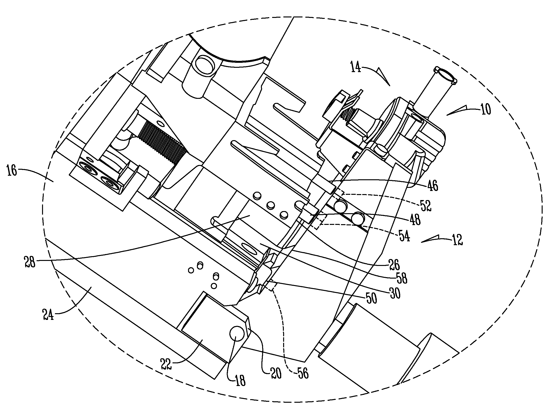
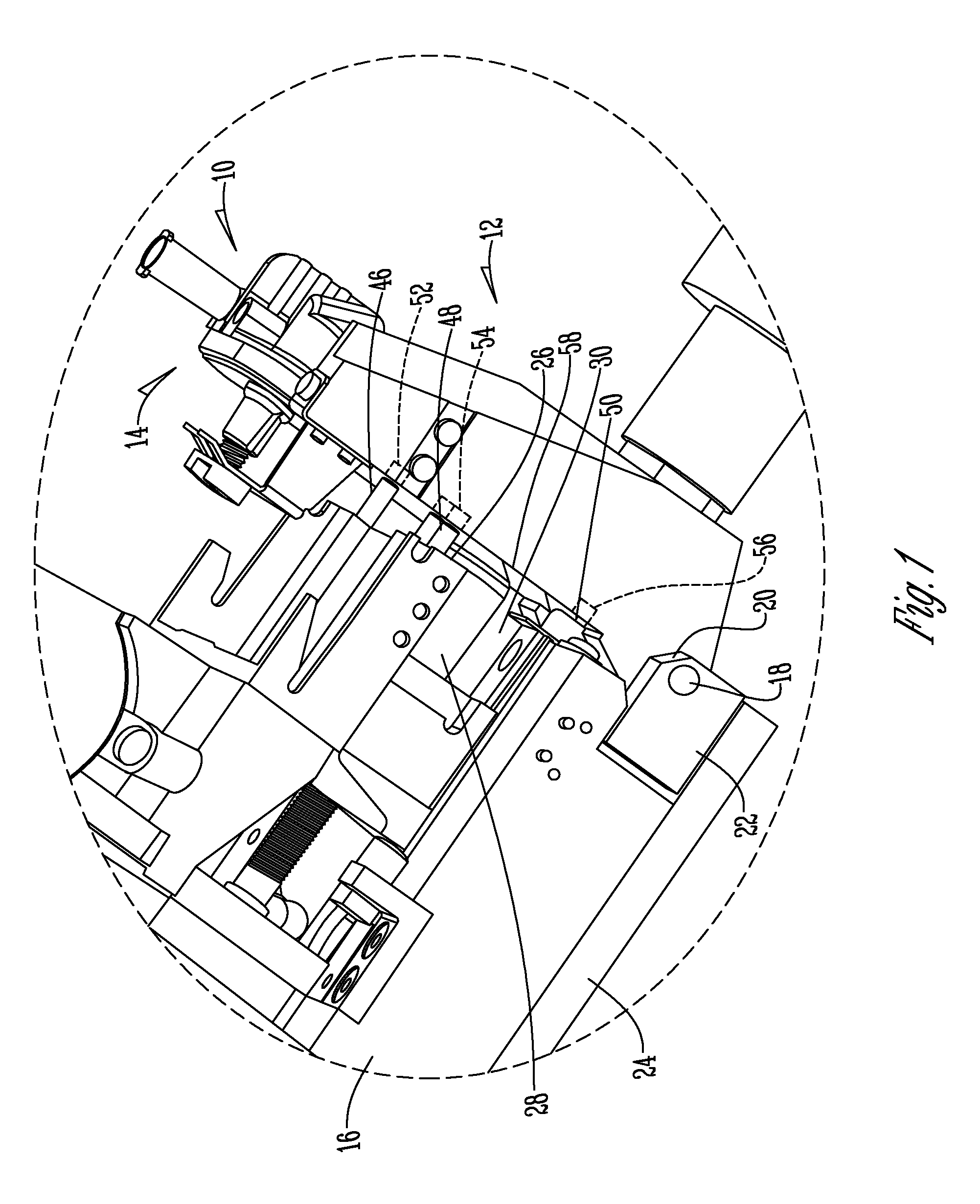
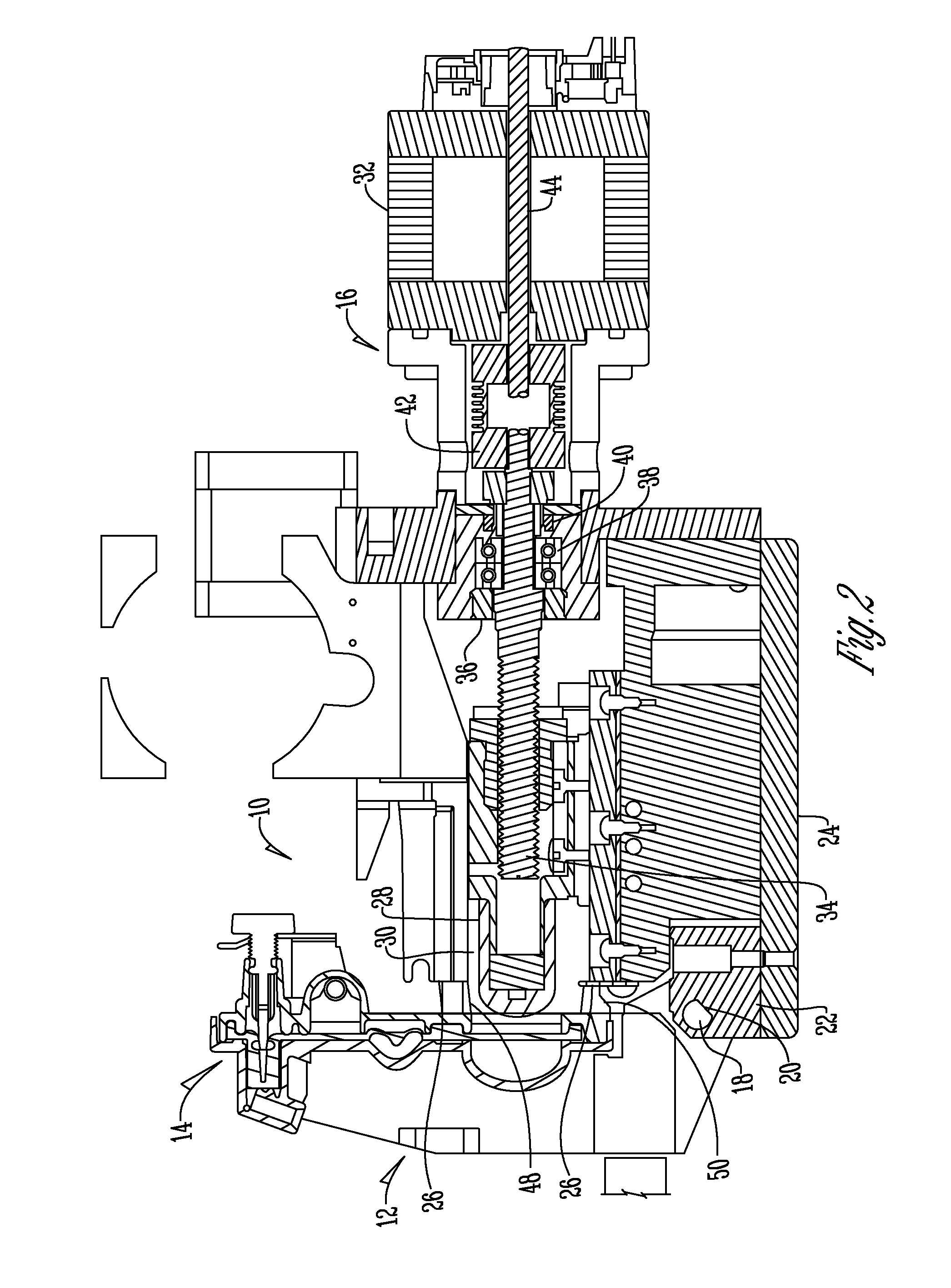
[0013]Referring to the Figures, the door mount stabilization system 10 includes a door 12 formed to receive a fluid administration set 14 such as a cassette or the like. The door 12 is pivotally attached to an infusion pump 16 by a pivot pin 18. The pivot pin 18 extends through a pivot pin opening 20 in a mounting block 22 that is secured to the base 24 of the infusion pump 16. The door 12 has a cavity 25 formed therein that receives a portion of the fluid administration set 14.

[0014]The infusion pump 16 has a front mechanism plate 26. Extending outwardly from the front mechanism plate 26 is a moveable plunger 28 that is aligned with and received by plunger opening 30. The plunger opening 30 has a centerline 31 that is coincident with the centerline of the cavity 25. Preferably, to improve flow performance of the pump 16, the plunger 28 is connected to a stepper motor 32 with a ball screw 34 that extends through a rotary nut 36, angular contact bearings 38, and a spacer 40 to a flex...


PUM


Abstract

A door mount system having an infusion pump with a front mechanism plate. Pivotally connected to the pump is a door. Extending outwardly from the front mechanism plate are a plurality of mounting pins that align with and are received within openings in a front face of the door.

Description

BACKGROUND OF THE INVENTION[0001]The present invention is directed to a door mount stabilization system and more particularly a door mount stabilization system for an infusion pump.[0002]Door mount systems for infusion pumps are known in the art. As flow rates and demands for accuracy have increased, problems with the door mount system have resulted. More specifically, as the pump actuator force has increased, the pump chamber actuation force has been insufficient to counteract the actuator force resulting in cassette body movement during pumping with a plunger. When the cassette body moves, flow efficiency is lowered, fluid output volume varies, and limitations are created with respect to pump flow rates and low flow continuity. Therefore, a need exists in the art for a system that addresses these deficiencies.[0003]An objective of the present invention is to provide a door mounting system that increases overall pump system stiffness.[0004]Another objective of the present invention...

Claims


Application Information

Patent Timeline
Patent Type & Authority Applications(United States)
IPC IPC(8): F04B7/02F04B17/03
CPCF04B17/03F04B7/02F04B53/16A61M2205/12A61M2205/121A61M5/14224
Inventor BALTEANU, VLAD R.JOHNSON, THOMAS D.
Owner ICU MEDICAL INC
Learn More