
Condition Detection and Display System, Condition Detection and Display Method, Control Program for Condition Detection and Display System, and Storage Medium Storing the Control Program

Inactive Publication Date: 2009-04-30
SHARP KK
View PDF4 Cites 77 Cited by
  • Summary
  • Abstract
  • Description
  • Claims
  • Application Information

AI Technical Summary

Benefits of technology

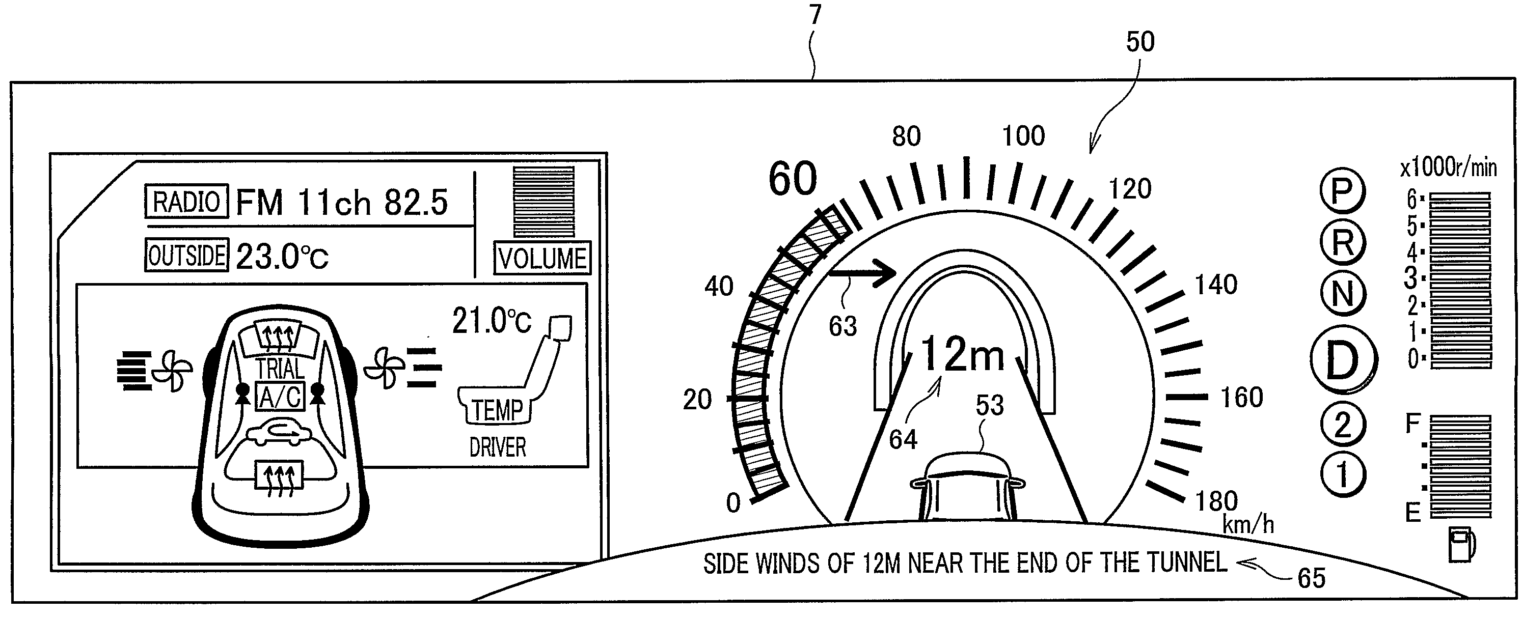
[0011]According to the above arrangement, the images showing the condition of the traveling means and surroundings around the traveling means are displayed at a position close to the speedometer. With this arrangement, it is possible to display sets of information that the driver should pay attention to in traveling together in one place. This allows the driver to check displays regarding the condition of the traveling means and surroundings around the vehicle without increase in the number of times driver's viewpoint moves. This reduces eyestrain of the driver. Further, it is possible to decrease the possibility that in traveling, the driver could miss the information that the driver should pay attention to. Still further, thanks to a small number of points to which the driver's viewpoint moves, the driver can drive with a more concentration to the front, thus contributing to a safe driving.
[0045]As described above, in the condition detection and display system of the present invention, the images showing the condition of the traveling means and the surroundings around the traveling means are displayed at the position close to the speedometer. With this arrangement, it is possible to display sets of information that the driver should pay attention to in traveling together in one place. This allows the driver to check displays regarding the condition of the traveling means and surroundings around the vehicle without increase in the number of times driver's viewpoint moves.

Problems solved by technology

Further, it is possible to decrease the possibility that in traveling, the driver could miss the information that the driver should pay attention to.

Method used


Image

  • Condition Detection and Display System, Condition Detection and Display Method, Control Program for Condition Detection and Display System, and Storage Medium Storing the Control Program
  • Condition Detection and Display System, Condition Detection and Display Method, Control Program for Condition Detection and Display System, and Storage Medium Storing the Control Program
  • Condition Detection and Display System, Condition Detection and Display Method, Control Program for Condition Detection and Display System, and Storage Medium Storing the Control Program

Examples


Embodiment Construction

[0058]One embodiment of the present invention is described below.

[0059]A condition detection and display system (present system) according to the present embodiment, which is provided in a vehicle (traveling means), detects a condition of the vehicle and surroundings around the vehicle and provides a driver of the vehicle with a detection result. Note that, in the present system, such information is displayed at a position close to a speedometer, thus allowing the driver to check the condition of the vehicle and the surroundings around the vehicle without increase in the number of times driver's viewpoint moves. This reduces eyestrain of the driver, prevents the driver from missing displayed information, allows the driver to drive with a more concentration to the front, thus contributing to a safe driving.

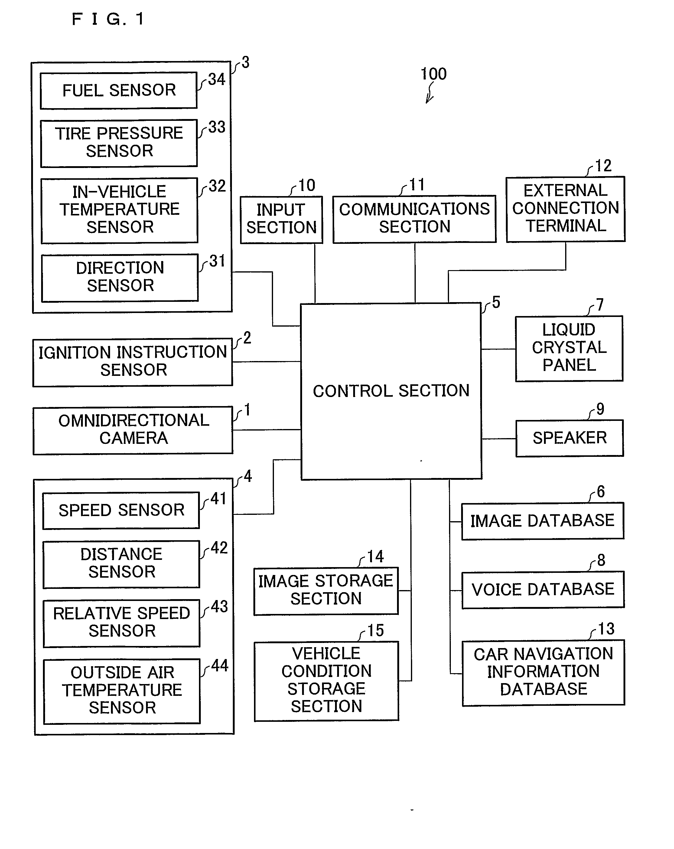
[0060]FIG. 1 is a block diagram schematically illustrating a configuration of the present system. As illustrated in FIG. 1, the present system 100 is composed of: an omnidirectiona...


PUM


Abstract

In a condition detection and display system (100), an omnidirectional camera (1), internal condition sensors (3), external condition sensors (4), and others detect a condition of a vehicle and surroundings around the vehicle, image data which is a detection result obtained by the aforesaid members and contains an image of the vehicle is selected from an image database (6), and the selected image data is displayed on a liquid crystal panel (7) at a position close to a display of a speedometer.

Description

TECHNICAL FIELD[0001]The present invention relates to a condition detection and display system, which is provided in traveling means such as a vehicle, for notifying a driver of information on the traveling means and surroundings around the traveling means, a condition detection and display method, a control program for condition detection and display system, storage medium storing the control program.BACKGROUND ART[0002]In recent years, many systems have been proposed, for example, in which various kinds of sensors are provided in a vehicle and information detected by the sensors is notified to a driver. For example, Patent Document 1 discloses a parking aiding device for teaching a driver in a vehicle a driving operation quantity for parking the vehicle in a desired parking section.[0003]Further, for example, Patent Document 2 discloses a vehicle-use confirmation device in which an imaging device captures information on surroundings around a vehicle or the like, and projects the i...

Claims


Application Information

Patent Timeline
IPC IPC(8): B60K35/00B60K31/18B60R1/00B60R11/02B60R11/04G08G1/16
CPCB60C23/0401B60K31/18B60K2350/2013B60L2250/16B60R1/00B60R11/0235G08G1/16B60R2300/105B60R2300/207B60R2300/301B60R2300/302B60R2300/305B60R11/04G08G1/166G08G1/167B60W2050/146B60K2360/21B60R1/27
Inventor YAMAMOTO, TAKESHIMIAKE, AKITAKAHASHI, TOSHIYAITOH, MEGUMIOKUDA, MITSUKAZUDOI, TAKESHI
Owner SHARP KK
Learn More