Eureka AIR delivers breakthrough ideas for toughest innovation challenges, trusted by R&D personnel around the world.

Lift truck fork aligning system with operator indicators

a technology for operator indicators and lift trucks, which is applied in the direction of lifts, lifting devices, transportation and packaging, etc., can solve the problems of improper engagement, damage to pallets, or tipping of material, and misjudge the elevation of forks, so as to achieve safe inserting of forks

Inactive Publication Date: 2009-05-07
EGGERT RICHARD T
View PDF9 Cites 26 Cited by
  • Summary
  • Abstract
  • Description
  • Claims
  • Application Information

AI Technical Summary

Benefits of technology

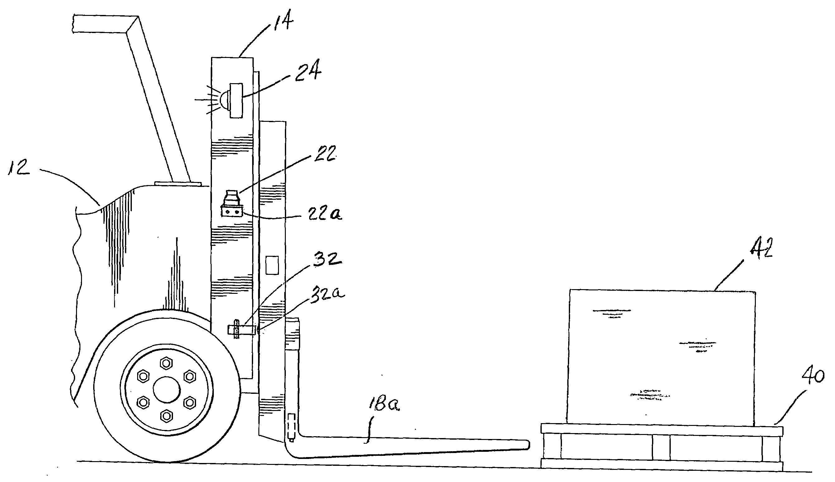
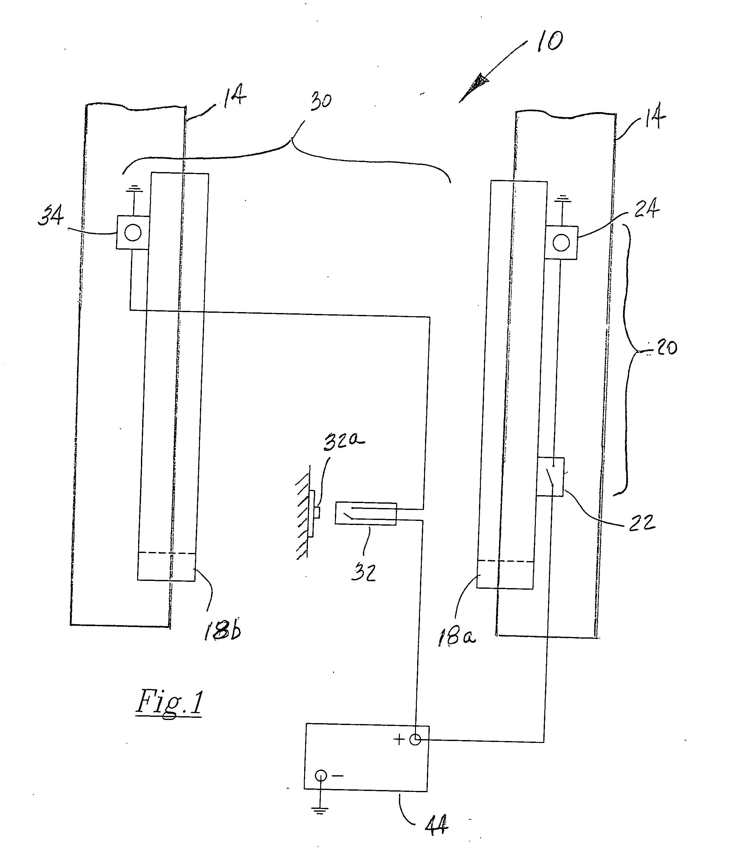
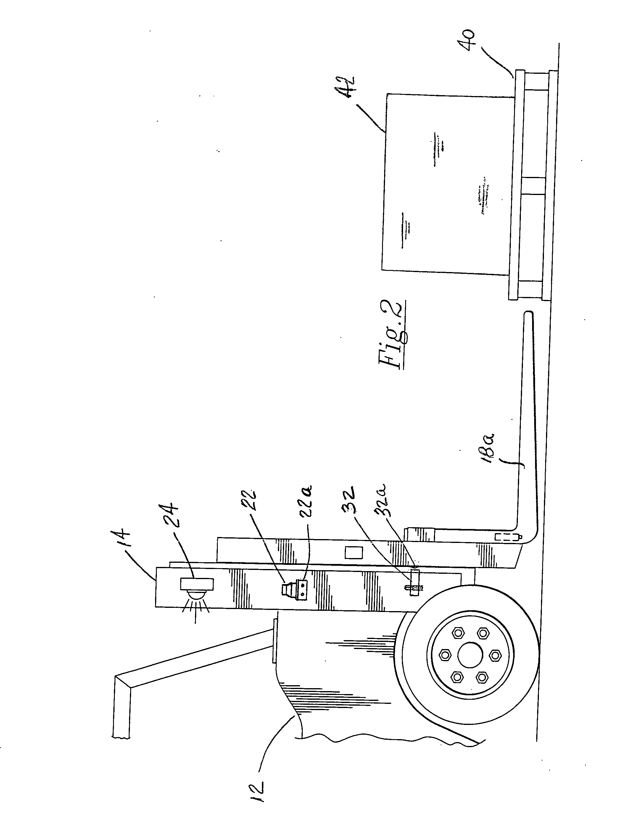
[0014]The apparatus includes positioning sensors appropriately mounted to the lift truck, indicator lamps for operator indication of faults or appropriate alignment, which work together to eliminate damage that occurs from “spearing” product loaded on pallets. In order to determine the proper position of the forks, the operator positions the mast and the forks to a lifting position and refers to the indicator lights for a determination of mast verticality, perpendicularity to the underlying surface, and minimal distance of the forks from the underlying surface. The system determines the proper position of both vehicle lift elements from a proximity sensor and a level sensor, which are mounted onto the vehicle, as visually indicated by the state of two independent indicator lights, one for proximity and one for perpendicularity.
[0017]Overall, the invention may be described as a sensor system for detecting both vertical and horizontal alignment of forklift vehicle forks, which sensor system is comprised of a first position detecting sensor for measuring and determining the verticality or perpendicularity of the forklift vehicle mast in respect to the underlying support surface, a second position detecting sensor for measuring and determining the vertical height of the forks above the underlying support surface; and first and second operator lamp indicators to show proper alignment of the forks with a pallet for operating the forklift vehicle to lift a pallet without the operator visually checking the position of the forks prior to inserting the forks under the pallet load support surface. As before, the first positioning sensor includes a level sensor located on the mast of the forklift vehicle for measuring and determining the verticality or perpendicularity of the mast to the underlying support surface. The second positioning sensor includes a proximity sensor mounted to the vertical portion of the mast juxtaposed opposite a metal tab protruding outward from and mounted to the vertical portion of the forks for measuring and determining a vertical height displacement measurement of the forks above the underlying support surface. Finally, the sensor system includes first and second operator lamp indicators that receive respective signals from the first and second position detecting sensors causing the indicators to alert the operator of the detected preconditions of fork alignment so the operator can insert the forks under the pallet load support surface and lift the load without causing damage to either the pallet or the load.
[0018]The invention may also be described as a method of safely inserting the forks of a lift vehicle under a load of material situated on a pallet. This method, for substantially simultaneously detecting the spatial relationships of the forks of a forklift vehicle, comprises the steps of providing a first sensing means for detecting the perpendicularity of the mast of the forklift vehicle to the underlying support surface, providing a second sensing means for detecting the vertical height displacement of the forks of the lift vehicle from the underlying support surface, and providing first and second indicator means for respectively indicating the combined detected preconditions to the forklift operator for operating the forklift vehicle to lift a pallet without the operator visually checking the position of the forks prior to inserting the forks under the pallet load support surface. Included in the method step of providing the first sensing means are the further steps of providing a verticality measurement from a level detection sensor mounted to the mast of the forklift vehicle and providing a level detection signal to one of the first and second indicator means to alert the operator of an alignment condition satisfactory for operation of the forklift vehicle. Included in the method step of providing the second sensing means are the further steps of providing a vertical height displacement measurement from an inductive sensor mounted to the vertical portion of the mast juxtaposed opposite a metal tab protruding outward from and mounted to the vertical portion of the forks and providing a height displacement signal to one of the first and second indicator means to alert the operator of an alignment condition satisfactory for operation of the forklift vehicle. Included in the method step of providing first and second indicator means are the further steps of providing respective signals from the first and second position detecting sensors of the measured alignment of the forks of the forklift vehicle to first and second operator lamp indicators and causing the indicators to alert the operator of the detected preconditions of fork alignment so the operator can insert the forks under the pallet load support surface and lift the load without causing damage to either the pallet or the load.

Problems solved by technology

The operator can sometimes misjudge the elevation of the forks and improperly engage the material with the tips of the forks, i.e., spearing, causing damage.
The result may be damage to, or tipping of the material from the pallet, or movement of the pallet relative to the lift truck preventing proper engagement.
Some lift trucks provide a fork tilt indicator; however, these indicators measure fork tilt relative to the truck's mast, but not relative to support surface proximity.
Further, monitoring fork tilt either by sensing the vertical component of the fork or at the heel of the fork will not take into consideration the deflection of the fork away from the mast due to the weight of the load.
Lift truck alignment systems in the past, only adjusted the height of the forks and did not have a vertical tilt system that allowed for the mast to move away from its vertical positioning.
Also, earlier lift systems only checked for the verticality of the forklift mast and not the actual lift fork itself.

Method used


Image

  • Lift truck fork aligning system with operator indicators
  • Lift truck fork aligning system with operator indicators
  • Lift truck fork aligning system with operator indicators

Examples


Embodiment Construction

[0021]The following detailed description is of the best presently contemplated mode of carrying out the invention. The description is not intended in a limiting sense, and is made solely for the purpose of illustrating the general principles of the invention. The various features and advantages of the present invention may be more readily understood with reference to the following detailed description taken in conjunction with the accompanying drawings.

[0022]Referring now to the drawings in detail, where like numerals refer to like parts or elements, there is shown in FIG. 1 a lift truck fork aligning and positioning system 10. The system 10 consists of dual fork alignment and positioning sensors that provide a verticality determination for the forklift mast and a predetermined height determination for the forks, and include indicator lamps for visual operability checks for the operator. Thus, the aligning and positioning system 10 comprises a first sensing means 20 that includes a ...


PUM


Abstract

A sensor system for substantially simultaneously measuring and detecting the verticality or perpendicularity of the forklift vehicle mast and the vertical height displacement of the forks. The sensor system then alerting the operator of the satisfactory assessment of the precondition alignment of the forks so that, without the need for visual checking of the vertical positioning of the forks, the operator can insert the forks under the pallet load support surface and lift the load without causing damage to either the pallet or the load.

Description

BACKGROUND OF THE INVENTION[0001]The invention resides in the field of leveling and alignment sensors and indicators for material handling vehicles. The present invention relates to a system for aligning and determining lift truck fork levelness with and distance from the underlying surface. The system of the present invention uses sensors to monitor and determine the lift truck fork alignment by measuring verticality and support surface proximity, and then affords the operator indications of these measurements in order to avoid damage to material on a pallet, or to the pallet itself.[0002]Lift trucks commonly have forks used to engage and lift material to be moved from one location to another location. The lift trucks usually have a manually operated valve to control the vertical movement of the forks by an operator. The operator of the lift truck adjusts the elevation of the forks in order to engage the pallet supporting the material. The material is frequently positioned on a pal...

Claims


Application Information

Patent Timeline
Patent Type & Authority Applications(United States)
IPC IPC(8): B66B3/02B66F9/06
CPCB66F9/07545
Inventor EGGERT, RICHARD T.
Owner EGGERT RICHARD T
Why Eureka
Eureka Blog
Learn More