Contaminated solvent recycling system

a solvent recycling and solvent technology, applied in the direction of distillation separation, water/sludge/sewage treatment, evaporator/condenser, etc., can solve the problem of less service over a longer period of time, and achieve the effect of large operations, low cost and energy saving

Active Publication Date: 2009-05-07
CHEMCHAMP BARBADOS
View PDF8 Cites 14 Cited by
  • Summary
  • Abstract
  • Description
  • Claims
  • Application Information

AI Technical Summary

Benefits of technology

[0003]It would therefore be desirable to provide a relatively inexpensive and energy efficient recycling system which could easily be placed in a service bay of an auto repair shop or similar type of establishment, as well as be adaptable for use in larger operations.
[0004]According to a first aspect of the invention, the need for removing sludge from the distillation vessel at the end of each batch is eliminated by confining the distillation zone to the top part of the distillation vessel by heating only the upper region of the vessel and providing a separate waste collection zone within the vessel. The sludge passes from the distillation zone to the waste collection zone where it accumulates, without impeding the efficiency of the heating medium. This maintains the efficiency of processing relatively small amounts of feed, whilst the overall size of the distillation vessel can be made as large as required to provide sufficient sludge capacity to accommodate sludge accumulating between periodic removal operations. If desired, for ease of handling, the waste collection zone and the distillation zone may be separate interconnected containers. In any case, the use of separate zones means that the frequency of manually removing the waste is greatly reduced, resulting in less service over a longer period of time.
[0005]According to a second aspect of the present invention, the contaminated solvent is processed automatically on a batchwise basis by cycling between the heating and cooling phases without user intervention between consecutive cycles. During the heating phase, solvent is boiled off and exits the distillation vessel. During the cooling phase, solvent vapour re-condenses in the distillation vessel and this change of state creates a vacuum which sucks more contaminated solvent into the vessel, which is then cycled again through the heating and cooling phases. This enables the distillation vessel to be maintained between relatively narrow temperature limits as the distiller cycles between the boiling and cooling stages. Thus, the change of the vapour state in the distillation vessel functions as a pump in sucking contaminated solvent into the vessel. For maximum efficiency, the volume of contaminated solvent being processed in each cycle is small, which is feasible because there is a constant supply of usable recycled solvent being generated by successive cycles for use as required. This means that in many cases, a relatively low-power energy source—for example a standard 110 v supply—can be used.

Problems solved by technology

In any case, the use of separate zones means that the frequency of manually removing the waste is greatly reduced, resulting in less service over a longer period of time.

Method used


Image

  • Contaminated solvent recycling system
  • Contaminated solvent recycling system
  • Contaminated solvent recycling system

Examples


Embodiment Construction

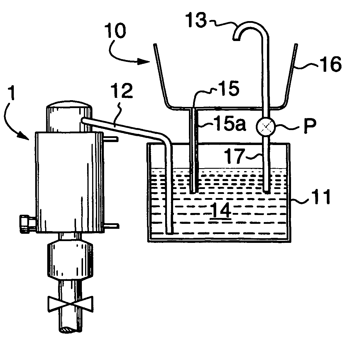
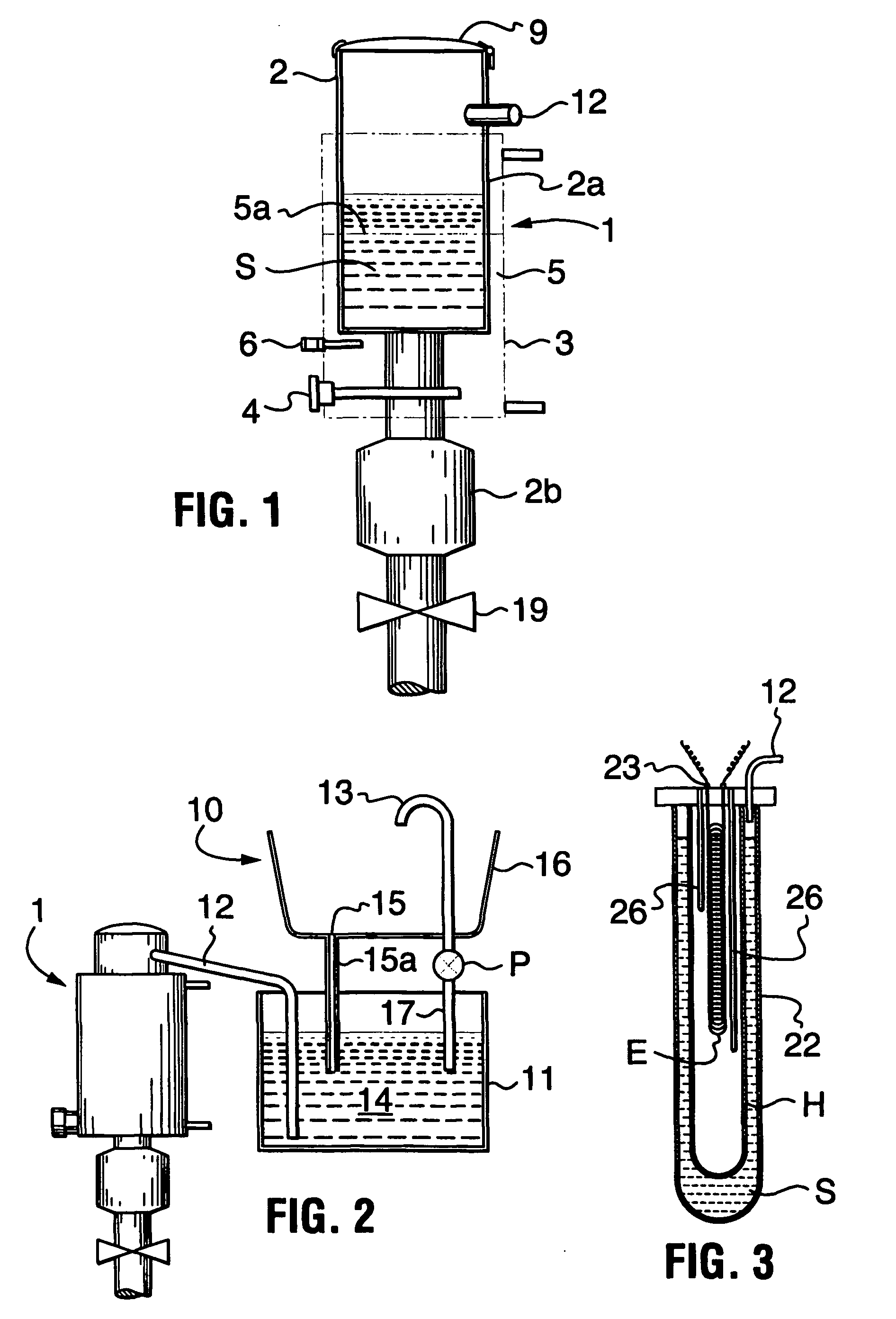
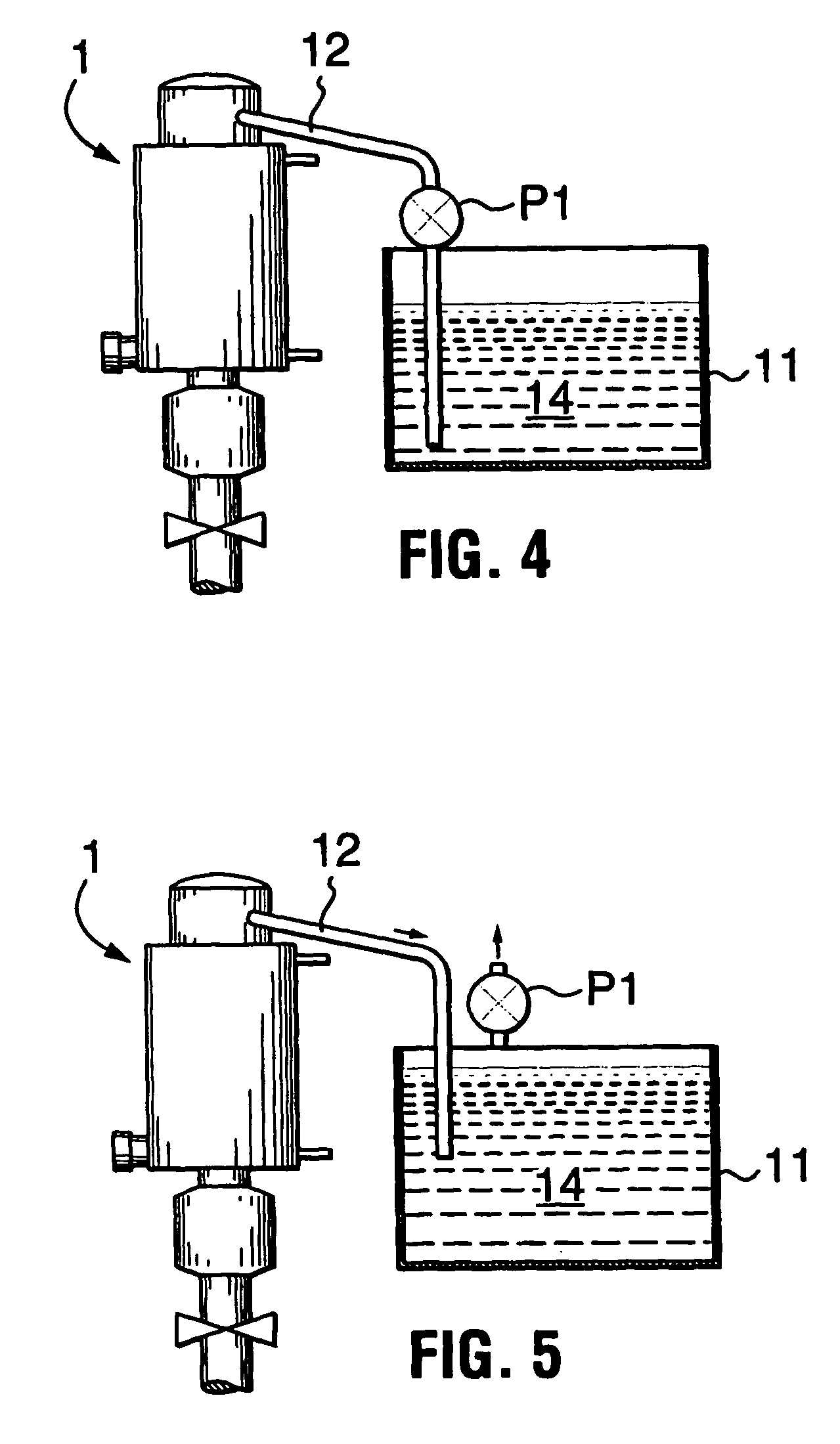
[0011]FIG. 1 shows schematically a distillation unit [1] in accordance with one embodiment of the invention, comprising a distillation vessel [2] having its upper region located in a heating jacket [3], contaminated solvent or a mixture of solvents [S] to be recovered being heated in a distillation region [2a] of the distillation vessel [2] adjacent the heating jacket [3] to generate solvent vapour. This solvent vapour then exits through a conduit [12] wherein it is condensed.

[0012]The upper part [2a] of the distillation vessel [2] sits within the heating jacket [3] containing an oil bath [5]. The heating jacket [3] is provided with one or more heating elements [4] immersed in the oil and, in operation, each heating element [4] heats the oil [5], which in turn heats the distillation zone formed in the upper part of the distillation vessel [2] at least until the solvent [S] within the distillation zone reaches its boiling point and vapour is generated. The distillation vessel [2] is ...


PUM

PropertyMeasurementUnit
massaaaaaaaaaa
internal pressureaaaaaaaaaa
pressureaaaaaaaaaa

Abstract

A contaminated solvent recycling system comprises a distillation vessel having a distillation zone and a separate waste collection zone and heating means for heating contaminated solvent feed within the distillation zone vessel to distill off the solvent. By separating the distillation zone from the waste collection zone, the distillation zone can be made small enough to process small consecutive batches of contaminated solvent feed whilst the waste collection zone can be made large enough to accommodate waste accumulating from the distillation process for extended periods of time between waste removal operations.

Description

BACKGROUND OF THE INVENTION[0001]Volatile solvents are used in many industrial processes in which the volatile solvent is used for cleaning purposes. As a result of such use the volatile solvent becomes contaminated with foreign matter. Such contamination may be in a variety of forms. For example, in an auto body shop, it would be in the form of paint residue from spray guns, which are normally cleaned with solvent in a gun washer. In an auto repair shop, the contaminants may well be oil and grease from the cleaning of mechanical parts. Due to the cost of such solvents, environmental concerns, and the cost of disposing of such contaminated volatile solvents, it is desirable to maximize the use that can be made of the solvent by removing the contamination from it by recycling it into the purified solvent form for further use in the industrial process. Various recycling systems exist for use in paint or body shops and as an example, reference is made to our published PCT application n...

Claims


Application Information

Patent Timeline
Patent Type & Authority Applications(United States)
IPC IPC(8): B01D3/00B01D5/00B01D1/00B01D3/10B01D3/42
CPCB01D1/0052B01D3/00B01D3/10Y10S159/901B01D5/00Y10S159/23Y10S159/16B01D3/42Y10T137/7838Y10T137/8326Y10T137/87056
Inventor HARLAND, CHARLESMOUNT, DENNIS WILLIAMFREDETTE, MATHIEU
Owner CHEMCHAMP BARBADOS
Why Eureka
Try Eureka