Energy distributing system

a technology of energy distribution system and distribution system, which is applied in the direction of combined combustion mitigation, lighting and heating apparatus, heating types, etc., can solve the problems of complex and expensive structural strengthening or expansion of existing district heating grid, and achieve the effects of reducing the heat loss to the surrounding environment, reducing the pumping work, and reducing the cost of construction

Active Publication Date: 2021-09-23
E ON SVERIGE
View PDF1 Cites 0 Cited by
  • Summary
  • Abstract
  • Description
  • Claims
  • Application Information

AI Technical Summary

Benefits of technology

[0008]By exchanging heat from the incoming flow of district heat transfer fluid to the outgoing flow of local heat transfer fluid in accordance with the above, a cheaper, less advanced and more energy efficient energy distributing system as compared with a traditional district heating system utilizing a district heating grid is achieved. For example, heat transfer losses will be reduced making the local energy distributing system more economical and energy efficient. Moreover, since heat transfer losses will be reduced, due to the relatively low temperature of the local heat transfer fluid distributing the energy in the local energy distribution system, constraints on the use of piping's for the conduits transporting the heat transfer fluid is reduced as compared with a traditional district heating system utilizing a district heating grid. Moreover, by setting the from the central heat exchanger outgoing flow of local heat transfer fluid at the temperature of 5-30° C. the cooling rate in the local energy distribution system will be reduced as compared with a traditional district heating system utilizing a district heating grid. The local energy distributing system also makes it possible to implement efficient energy distribution solutions in expansion areas where existing district heating grids are weak or difficult to expand. Strengthen or expanding existing district heating grids is both expensive and complicated. Moreover, by reducing the cooling rate of the energy distribution system the flow rate of the heat transfer fluid is reduced. Hence, the overall demand on the pumping in the energy distribution system is reduced. This will further reduce the complexity of the energy distribution system as compared with a traditional district heating system utilizing a district heating grid.
[0011]Each of the plurality of local heating systems may be configured to return local heat transfer fluid having a temperature being in the range of −5-15° C. By conducting local heat transfer fluid having a temperature in this temperature range, heat loss to the surroundings may be reduced. Moreover, thermal energy of the surroundings may even be absorbed by the local heat transfer fluid flowing in the local return conduit. The surroundings of the return conduit is typically ground since the return and feed conduits typically is arranged in the ground along the majority of their paths.
[0012]The local feed conduit together with the local return conduit may have a heat transfer coefficient greater than 2.5 Watt per meter&Kelvin, W / (mK), when parallel arranged in ground. This value of the heat transfer coefficient is estimated when the local feed and return conduits are parallel arranged within a distance of one meter from each other in ground having an average annual temperature of 8° C. and the arithmetic average temperature of the local feed and return conduits are 8-10° C. By this, thermal heat from the surroundings may be picked up by the local feed conduit and / or the local return conduit. Moreover, cheap un-insulated plastic pipes may be used for the local feed conduit and / or the local return conduit. Moreover, thermal energy of the surroundings may easily be absorbed by the local heat transfer fluid flowing in the local return conduit.
[0013]At least some of the plurality of local heating systems may comprises a local circulation pump connected between the inlet and the outlet of the respective local heating system for circulating local heat transfer fluid in the local feed and return conduits. A system with distribute pumping of the local heat transfer fluid are thus provided. Such a system is less vulnerable. This since upon failure in one or more of the local circulation pumps the rest of the system will still be operational. Moreover, by distributing the pumping over the plurality of local circulation pumps smaller and cheaper circulation pumps may be utilized.
[0016]The central heat exchanger may be configured to exchange heat such that the district heat transfer fluid returned to the district return conduit is having a temperature of 5-20° C., preferably 5-10° C. By returning district heat transfer fluid of this low temperature the cooling performed in the central heat exchanger 21 can be as great as approx 100° C. (depending of the temperature of the incoming district heat transfer fluid feed through the district feed conduit). This high degree of cooling performed in the central heat exchanger will reduce the heat losses in the district heating grid. Moreover, it will reduce the degree of pumping needed in the district heating grid.
[0017]The local energy distributing system may further comprise one or more local cooling systems having an inlet connected to the outlet of one of the plurality of local heating systems, wherein the one or more local cooling systems are configured to extract heat from a building. By this a combined heating and cooling system is provided. Moreover, comfort heating and comfort cooling is provided at the same time in a simple and cost effective manner using only one of energy distribution grid.

Problems solved by technology

Strengthen or expanding existing district heating grids is both expensive and complicated.

Method used


Image

  • Energy distributing system
  • Energy distributing system
  • Energy distributing system

Examples


Embodiment Construction

[0034]The present invention will now be described more fully hereinafter with reference to the accompanying drawings, in which currently preferred embodiments of the invention are shown. This invention may, however, be embodied in many different forms and should not be construed as limited to the embodiments set forth herein; rather, these embodiments are provided for thoroughness and completeness, and to fully convey the scope of the invention to the skilled person.

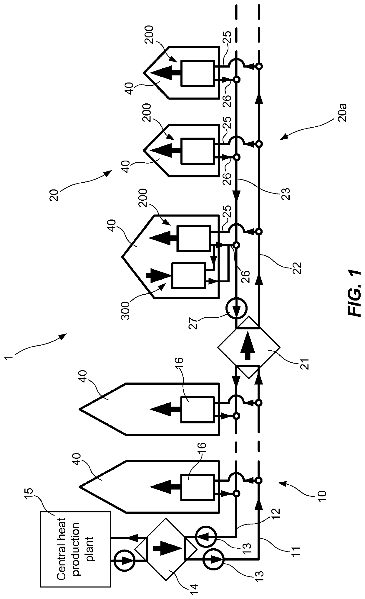
[0035]In connection with FIG. 1 an energy distribution system 1 will be discussed. The energy distribution system 1 comprises a district heating grid 10 and a local energy distributing system 20. The local energy distributing system 20 is connected to the district heating grid 10 via a central heat exchanger 21.

[0036]The district heating grid 10 is formed by one or several hydraulic networks configured to deliver district heat transfer fluid to district heating substations 16 which are arranged in buildings 40 such as of...


PUM


Abstract

A local energy distributing system includes a local feed conduit; a local return conduit; a central heat exchanger connected to a heating grid having a feed conduit for an incoming flow of heat transfer fluid having a first temperature in the range of 50-120° C., and a return conduit for a return flow of heat transfer fluid having a second temperature, the second temperature being lower than the first temperature, wherein the central heat exchanger is configured to exchange heat from the incoming flow of heat transfer fluid to an outgoing flow of local heat transfer fluid in the local feed conduit. The system also includes a plurality of local heating systems, each having an inlet connected to the local feed conduit and an outlet connected to the local return conduit, wherein each local heating system is configured to provide hot water and / or comfort heating to a building.

Description

FIELD OF THE INVENTION[0001]The invention relates to an energy distributing system.BACKGROUND OF THE INVENTION[0002]Nearly all large developed cities in the world have at least two types of energy distribution grids incorporated in their infrastructures: one grid for providing heating and one grid for providing cooling. The grid for providing heating may e.g. be used for providing comfort and / or process heating, and / or hot tap water preparation. The grid for providing cooling may e.g. be used for providing comfort cooling and / or process cooling.[0003]A common grid for providing heating is a gas grid or an electrical grid providing comfort and / or process heating, and / or hot tap water preparation. An alternative grid for providing heating is a district heating grid. The district heating grid is used for providing heated heat transfer fluid, typically in the form of water, to buildings of the city. A centrally placed heating and pumping plant is used for heating and distributing the he...

Claims


Application Information

Patent Timeline
Patent Type & Authority Applications(United States)
IPC IPC(8): F24D10/00F24D19/10
CPCF24D10/006F24D19/1006F24D19/1072Y02B30/17F24D2200/13F24D2220/06F24D2200/12F24D10/003F24D11/0207Y02E20/14
Inventor ROSENQVIST, FREDRIK
Owner E ON SVERIGE
Why Eureka
Try Eureka