

Laser brazing improvement with twinspot
a twin-spot, laser brazing technology, applied in the direction of laser beam welding apparatus, manufacturing tools, solventing equipment, etc., can solve the problems of affecting the quality of laser brazing, and forming pores of the filler material,
Active Publication Date: 2009-05-07
VOLVO CAR CORP
View PDF3 Cites 14 Cited by
- Summary
- Abstract
- Description
- Claims
- Application Information
AI Technical Summary
Benefits of technology
[0011]c. passing said laser brazing head along said junction such that said first laser beam melts said filler material to at least
Problems solved by technology
However, one problem with current laser brazing processes is that, upon cooling and solidifying, the filler material forms pores, some of which can break the surface of the brazed joint.
Surface-breaking pores can be eliminated by mechanically working the brazed joint (e.g. polishing, grinding or filling), but this technique is time-consuming and labour-intensive.
Pores in the brazed joint will tend to have negative effects on the physical properties (e.g. strength) of the joint, and surface-breaking pores are a particular problem in applications requiring a smooth finish.
Method used
View moreImage
Smart ImageViewing Examples

Examples
example
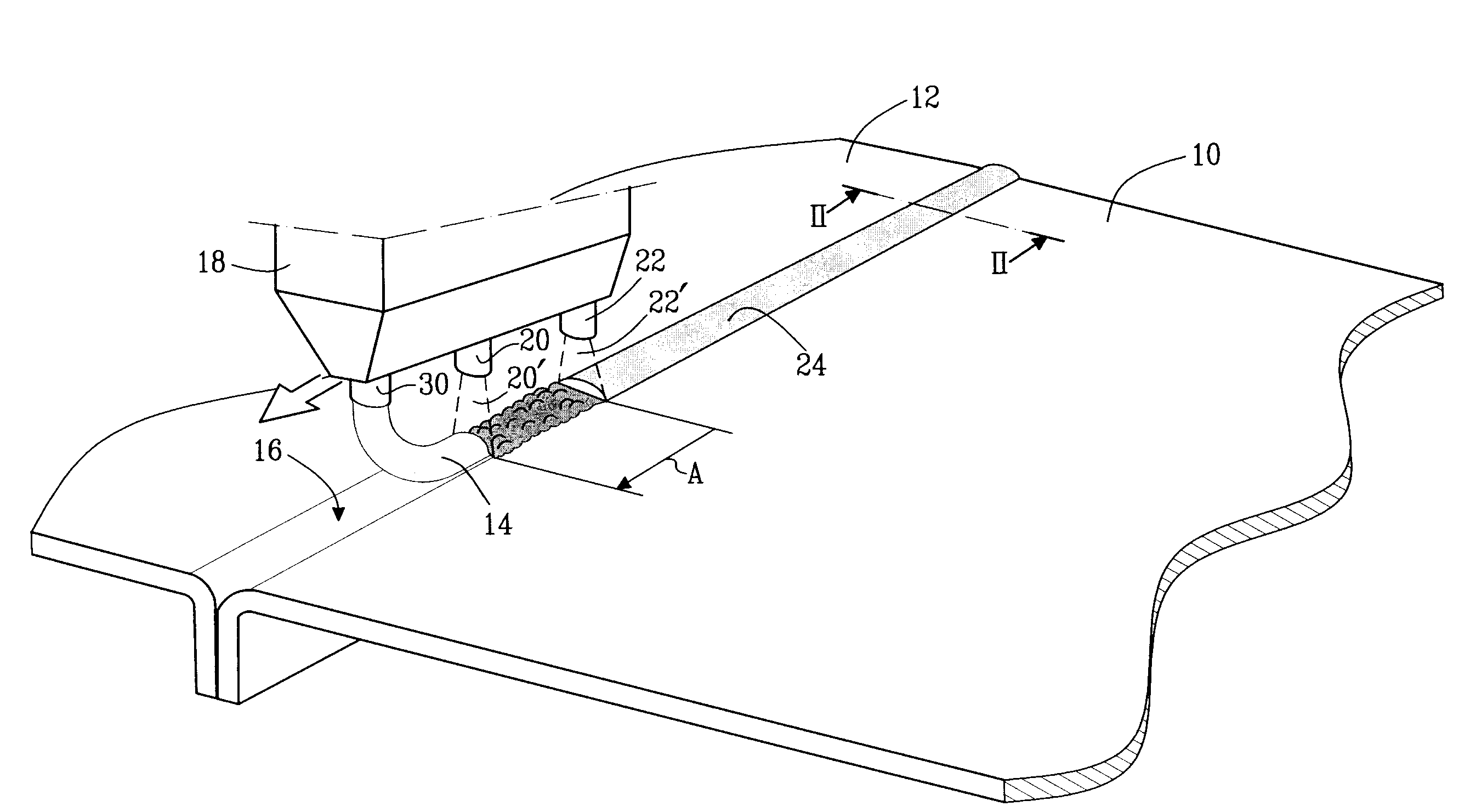
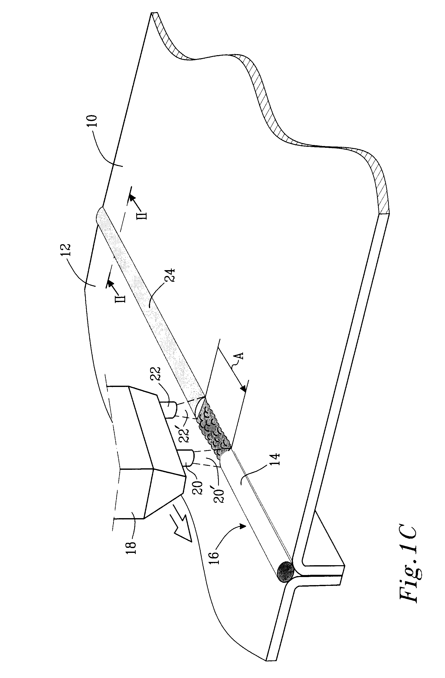
[0048]Typically the set-up for laser brazing two materials together includes two steel sheet materials and a copper alloy filler wire, CuSi3. The two materials are clamped together with a clamping wheel or by a movable / indexing fixture to form a joint without gaps. The twinspot beam is usually generated by using a wedge lens internally in the standard laser optic, changing the optical path of a part of the beam (typically 20%), creating the second spot. Depending on the brazing speed, the distance between the two spots needs to be adjusted to get optimum effect. At a brazing speed of 2 m / min, a typical distance between the two spots are 8-10 mm in order to get a good result, with the second beam spot tracing the center of the seam
Login to View More PUM
| Property | Measurement | Unit |
|---|---|---|
| Distance | aaaaa | aaaaa |
| Distance | aaaaa | aaaaa |
| Distance | aaaaa | aaaaa |
Abstract
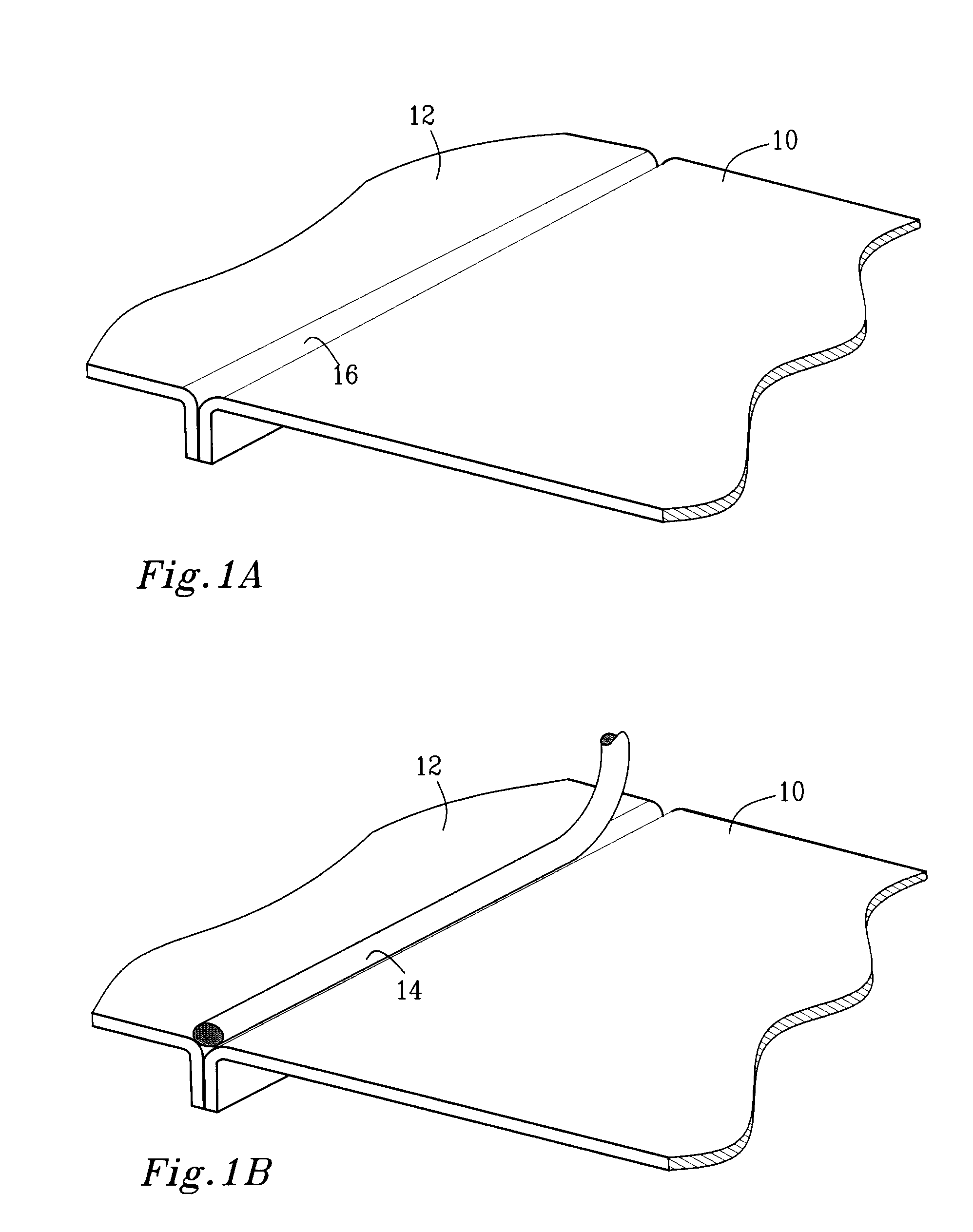
The present invention provides a method for laser brazing a first member to a second member using a laser brazing head. The laser brazing head has means for generating a first laser beam and a second laser beam. The method comprises the steps of: arranging the first member in contact with the second member such that a junction is formed there-between; providing a filler material in the vicinity of said junction, and passing the laser brazing head along the junction such that the first laser beam melts the filler material to at least partially fill said junction to form a brazed joint. The second laser beam then effects a post heat treatment of the brazed joint.
Description
TECHNICAL FIELD[0001]The present invention relates to a method of laser brazing, using a post heat treatment to reduce or eliminate the presence of defects in the brazed joint.BACKGROUND OF THE INVENTION[0002]Brazing is a common technique used to join two close-fitting surfaces. It involves placing a filler material such as a metal or metal alloy in the junction between two surfaces and applying heat so that the filler material melts. The filler material can then flow at least partially into the junction and solidify to form a brazed joint, thus bonding the two surfaces tightly together. The filler material and the material of the surfaces often partially dissolve one another at the interface, leading to strong bonding at a molecular level.[0003]In laser brazing, the filler material is heated with a laser, which can provide accurate, controllable heating. However, one problem with current laser brazing processes is that, upon cooling and solidifying, the filler material forms pores,...
Claims
Login to View More Application Information
Patent Timeline
 IPC IPC(8): B23K26/24B23K26/42B23K26/00B23K26/21
CPCB23K1/0056
InventorPALMQUIST, NICLASLINDAHL, PERTODAL, URBANLAURILA, ESA P.HOPKINS, GLEN PETERSTROMBLAD, MARTINSTEINERT, REIKJONSSON, LUKAS
OwnerVOLVO CAR CORP