Method of controlling electric conduction through thermal heat and thermal printer

a technology of thermal printer and electric conduction, which is applied in the direction of printing, instruments, measurement devices, etc., can solve the problems of ink ribbon being disadvantageously broken by heating, printing size deviating from a preset design value, and blanking in a part of the print target medium, so as to increase or reduce the number of print lines

Active Publication Date: 2009-05-07
NISCA KK
View PDF5 Cites 9 Cited by
  • Summary
  • Abstract
  • Description
  • Claims
  • Application Information

AI Technical Summary

Benefits of technology

[0020]Furthermore, according to the present aspect, the correction value calculating means may further arithmetically process the correction value into an integer value. The determination section may

Problems solved by technology

Thus, disadvantageously, a print size may deviate from a preset design value (expansion or contraction may occur).
In case the entire surface of the print target medium is printed, if a printing continues in a condition that the print size varies as described above to displace the thermal head from an end of the print t

Method used


Image

  • Method of controlling electric conduction through thermal heat and thermal printer
  • Method of controlling electric conduction through thermal heat and thermal printer
  • Method of controlling electric conduction through thermal heat and thermal printer

Examples


Embodiment Construction

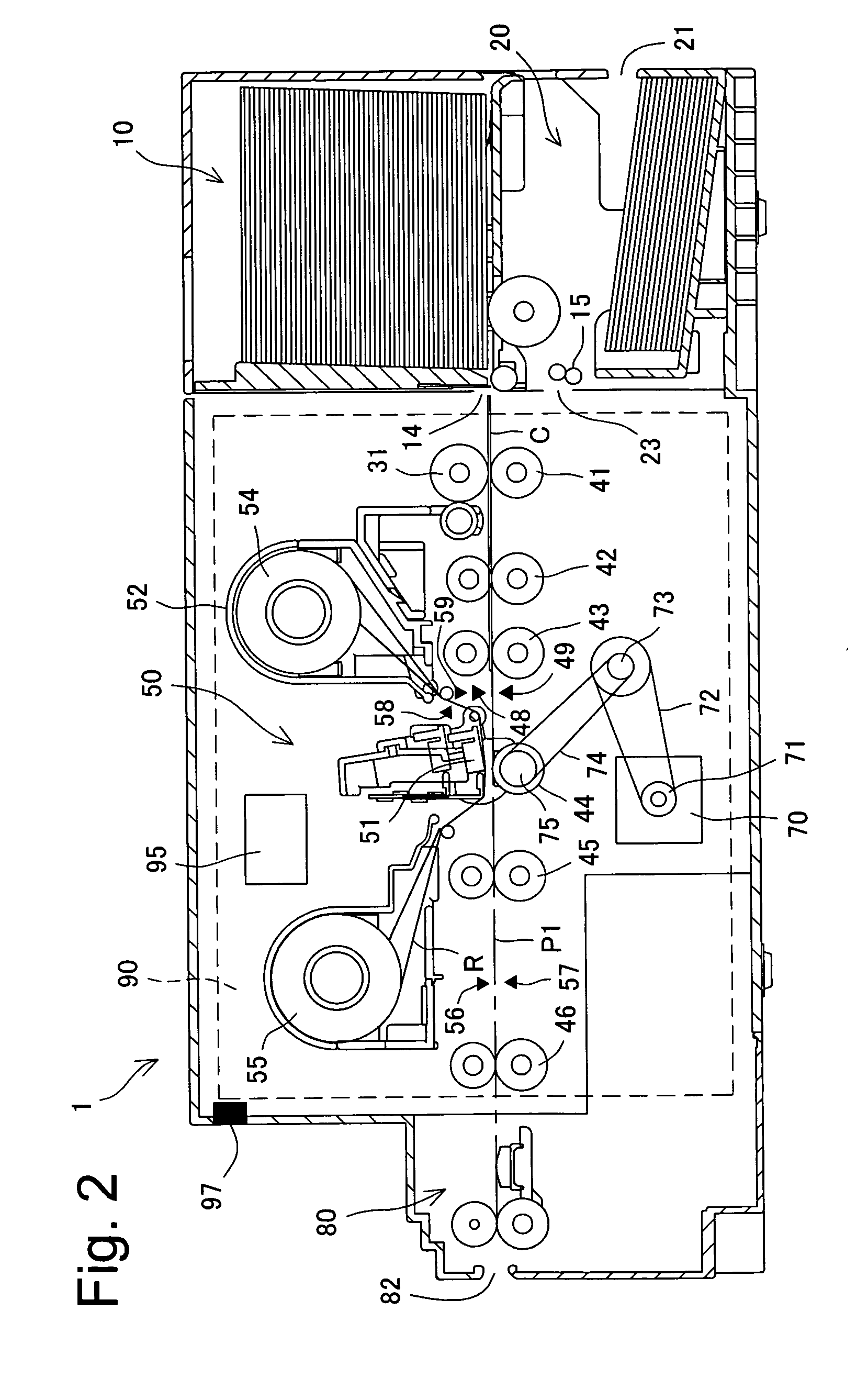
[0031]With reference to the drawings, embodiments will be described in which the present invention is applied to a thermal printer including a function of printing and recording texts or images on a card-like recording medium or a card-like print medium (hereinafter simply referred to as a card) and a function of performing a magnetic recording process on a magnetic stripe portion of the card.

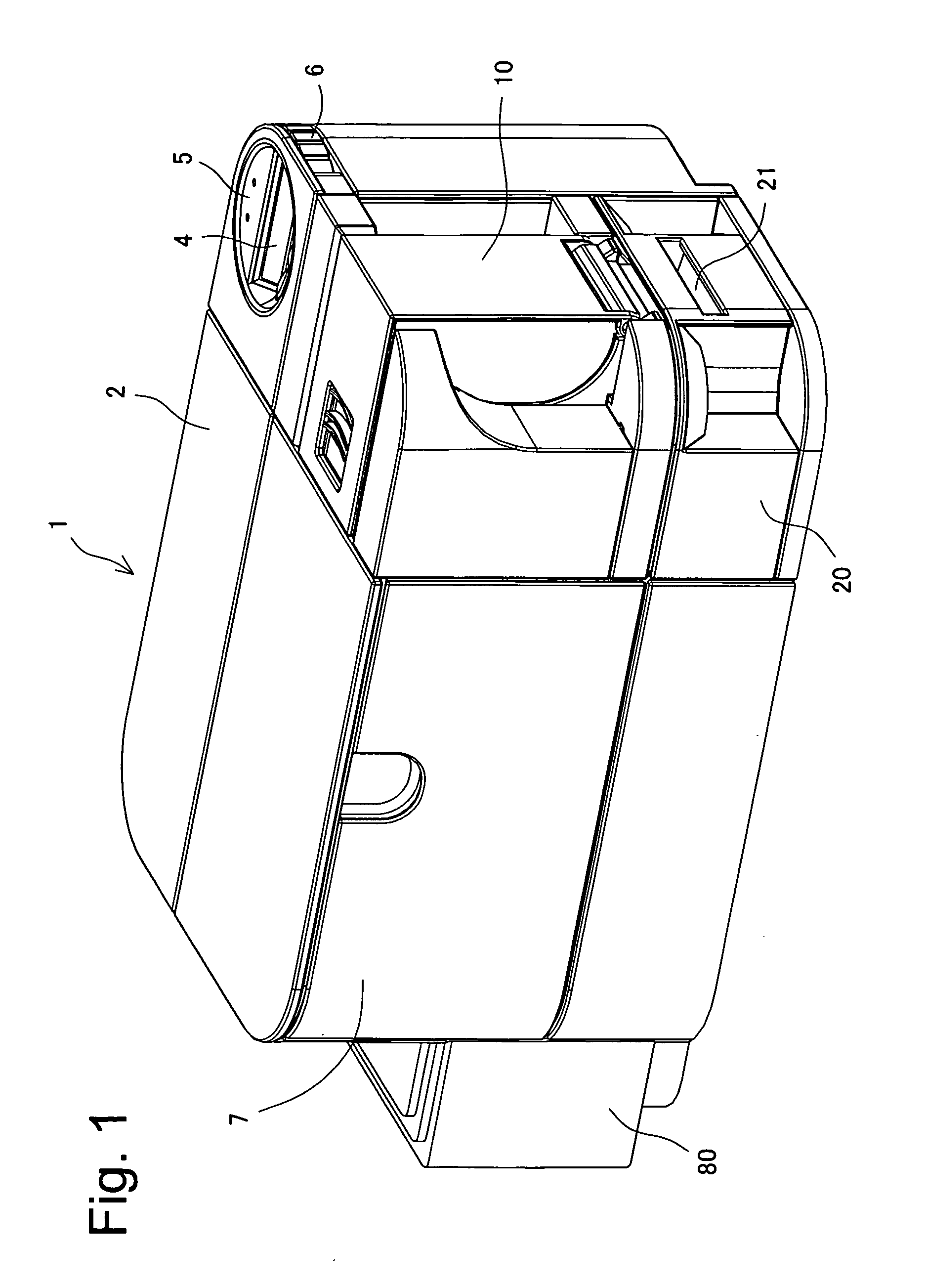
[0032]As shown in FIG. 7, a printer apparatus 1 according to the present embodiment is connected to a higher-order apparatus 100 (for example, a host computer such as a personal computer) via an interface (not shown in the drawings) so that the upper apparatus 100 can transmit print recording data, magnetic recording data, or the like to the printer apparatus 1 to instruct the printer apparatus 1 to perform a recording operation or the like. As described below, the printer apparatus 1 includes an operation panel section (operation display section) 5 (see FIGS. 7 and 1) and is not only instructe...


PUM


Abstract

A thermal printer detects an environmental temperature, and directly or indirectly detects a change in tension of an ink ribbon R. A correction value is read or calculated according to at least one of the detected environmental temperature and the detected change in the tension of the ink ribbon R. Thermal energy of each heating element in the thermal head is controlled based on the correction value so as to adjustably increase or reduce number of print lines on a print medium in a sub-scanning direction.

Description

BACKGROUND OF THE INVENTION AND RELATED ART[0001]The present invention relates to a method of controlling electric conduction through a thermal head as well as a thermal printer, in particular, a method of controlling electric conduction through a thermal head as well as a thermal printer which enable optimum electric conduction in an overall printing process executed on a card-like print medium.[0002]To produce a card-like print medium, for example, a credit card, a cache card, a license card, or an ID card, a printing apparatus as a thermal printer is conventionally used which allows a thermal head to perform thermal transfer on the card via a thermal transfer film with an ink layer to print and record desired images, texts, or the like. Such an apparatus is disclosed in, for example, Japanese Patent No. 3366791.[0003]Furthermore, for example, Japanese Patent Application Publication No. 7-214843 discloses a thermal printer that prints the entire surface of the card-like print medi...

Claims


Application Information

Patent Timeline
IPC IPC(8): B41J32/00B41J2/375
CPCB41J2/375B41J29/38B41J29/02
Inventor MOCHIZUKI, HIROSHI
Owner NISCA KK
Why Eureka
Try Eureka