Liquid ejection control device, liquid ejection system, and control method

a control device and liquid ejection technology, applied in the field of liquid ejection control devices, can solve the problems that the volume of excision of the excision target cannot be changed, and achieve the effect of improving user-friendliness

Active Publication Date: 2016-08-04
COLUMBIA PEAK VENTURES LLC
View PDF0 Cites 5 Cited by
  • Summary
  • Abstract
  • Description
  • Claims
  • Application Information

AI Technical Summary

Benefits of technology

[0010]An advantage of some aspects of the invention is to propose a technique in which the strength of a p...

Problems solved by technology

However, it is found that even though the characteristic value of the drive voltage to be instructed through the operation unit is changed, there may be a case where excisional circumstances such as the depth of excision and the volume of excision of the excision target ...

Method used


Image

  • Liquid ejection control device, liquid ejection system, and control method
  • Liquid ejection control device, liquid ejection system, and control method
  • Liquid ejection control device, liquid ejection system, and control method

Examples


exemplary embodiment 1

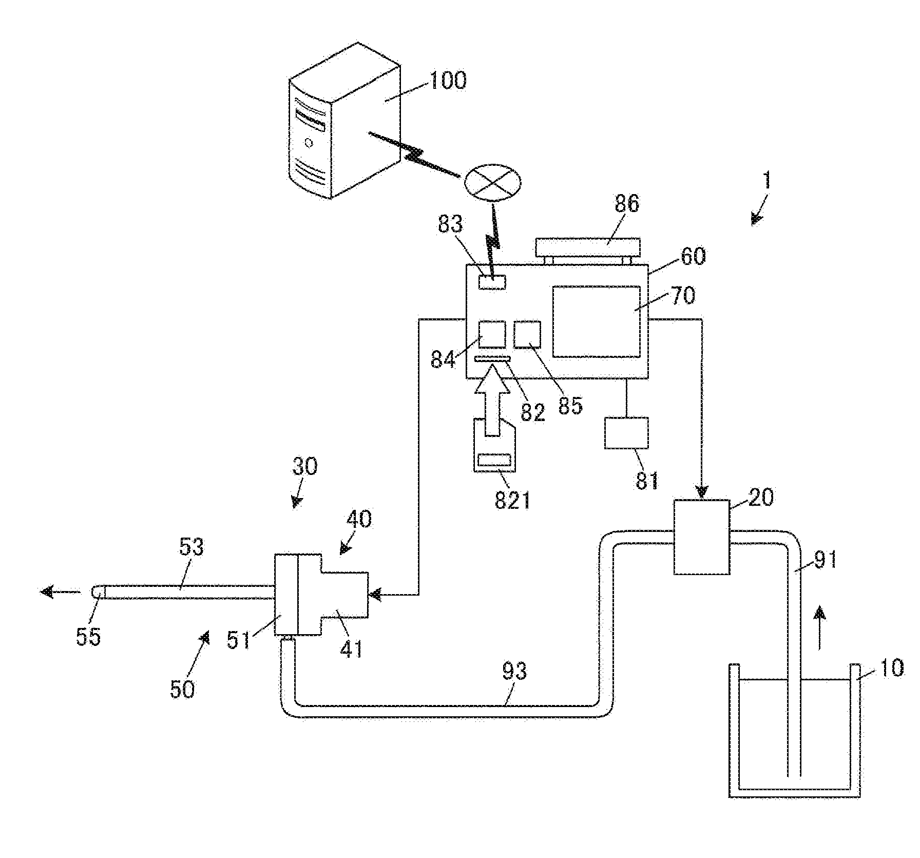
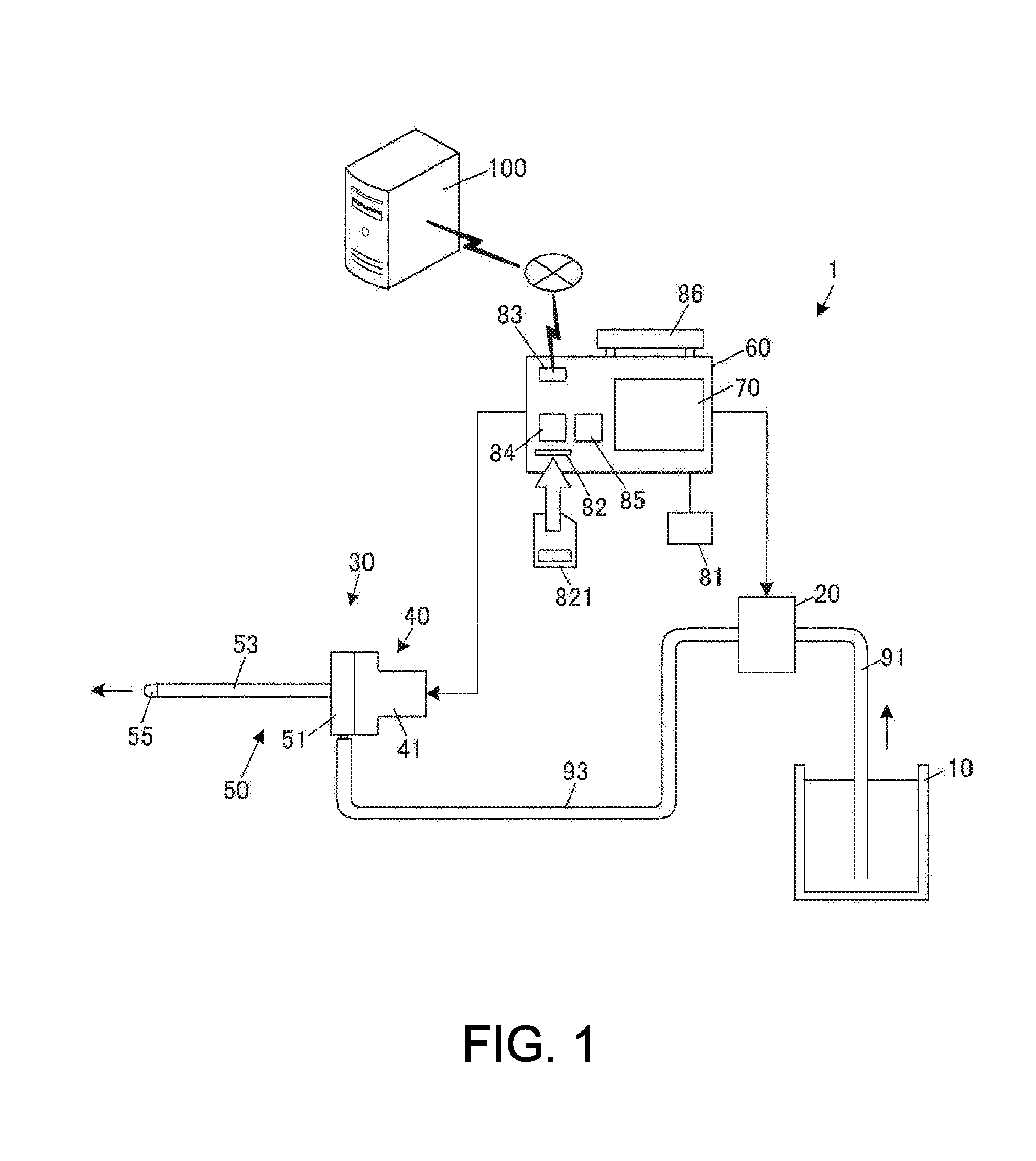
[0115]First, description will be given regarding Exemplary Embodiment 1. FIG. 12 is a diagram illustrating an operation panel 70-1 included in a liquid ejection control device 60-1 in Exemplary Embodiment 1. As illustrated in FIG. 12, an energy dial 711 as a first operation unit, a repetitive frequency dial 713 as a second operation unit, a power button 72, an ejection button 73, a pump drive button 74, and a liquid crystal monitor 75 are arranged in the operation panel 70-1.

[0116]The energy dial 711 is used for inputting an instruction value of energy E (an energy instruction value) which is a first instruction value. For example, dial positions in five stages having graduated scales “1” to “5” are configured to be able to be selected. An operator performs the increasing / decreasing operation of the energy E in five stages by switching the dial position of the energy dial 711. For example, the energy instruction values are allocated respectively for the dial positions in advance so ...

exemplary embodiment 2

[0153]Next, description will be given regarding Exemplary Embodiment 2. The same reference numerals and signs will be applied to the portions similar to those in Exemplary Embodiment 1. FIG. 17 is a diagram illustrating an operation panel 70-2 included in a liquid ejection control device 60-2 in Exemplary Embodiment 2. As illustrated in FIG. 17, the energy dial 711, the repetitive frequency dial 713, a rising frequency dial 715a as a third operation unit, the power button 72, the ejection button 73, the pump drive button 74, and the liquid crystal monitor 75 are arranged in the operation panel 70-2.

[0154]The rising frequency dial 715a is used for inputting an instruction value of the rising frequency (a rising frequency instruction value) as a third instruction value. For example, dial positions in five stages having graduated scales “1” to “5” are configured to be able to be selected. Similar to the repetitive frequency dial 713, the rising frequency dial 715a may also be configure...

modification example

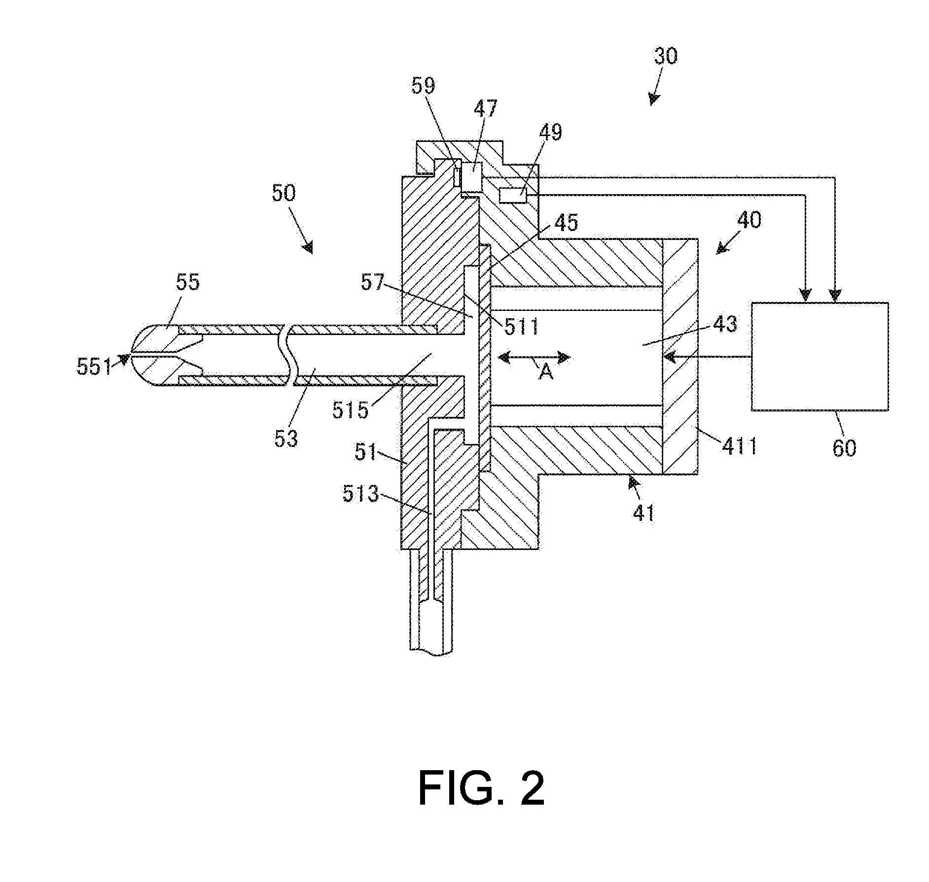
[0167]Hereinbefore, embodiments regarding two Exemplary Embodiments are described. However, a form which can be applied to the invention is not limited to the above-described forms. For example, in the embodiments described above, the energy conversion tables are stored in the storage unit 67 of the liquid ejection control device 60, and the fitted energy conversion table of the ejection tube section ID allocated for the ejection tube section 50 which is mounted in the main body section 40 is used while being under control performed by the piezoelectric element 43. In contrast, the fitted energy conversion table is not limited to the configuration of being readout from the storage unit 67 of the liquid ejection control device 60.

[0168]For example, the fitted energy conversion table may be configured to be acquired from the external server apparatus 100 which stores and manages the energy conversion table for each of the ejection tube section ID. In this case, the ejection tube secti...


PUM


Abstract

In a liquid ejection control device, an ejection tube section type acquisition unit discriminates an ejection tube section type of an ejection tube section mounted in a main body section, and acquires a fitted correspondence relationship fitting the discriminated ejection tube section type. A voltage amplitude setting unit sets a voltage amplitude of a drive voltage waveform so as to cause kinetic energy to meet an energy instruction value input by using an energy dial based on a rising index value related to rising of the drive voltage waveform and a repetitive frequency instruction value input by using a repetitive frequency dial with reference to the fitted correspondence relationship.

Description

BACKGROUND[0001]1. Technical Field[0002]The present invention relates to a liquid ejection control device and the like which control a liquid ejection device ejecting a liquid in a pulsed state by using a piezoelectric element.[0003]2. Related Art[0004]There is a known technology in which a liquid is ejected in a pulsed state and an excision target is excised. Ejection of a pulsed liquid is a jet flow of the liquid which is ejected from a nozzle in a pulsating manner and will be appropriately referred to as “a pulsed liquid jet” in this specification.[0005]There are various purposes of the pulsed liquid jet. For example, JP-A-2005-152127 discloses a proposed technology in which the pulsed liquid jet is utilized for a surgical operation in the medical field. In this case, the excision target is a living tissue, and the liquid is a physiological salt solution.[0006]As a mechanism which generates a pulsed liquid jet, there is a known mechanism in which a piezoelectric element is used. ...

Claims


Application Information

Patent Timeline
IPC IPC(8): B41J2/045
CPCA61B90/96A61B17/3203A61B2017/00154A61B2017/00181B41J2/04588A61B2017/00473A61B2017/00482B41J2/04581A61B2017/00194A61B17/3205B26F3/004A61B2017/00017
Inventor KARASAWA, JUNICHI
Owner COLUMBIA PEAK VENTURES LLC
Why Eureka
Try Eureka