Objective Lens Actuator and a Disc Apparatus Using the Same Therein

a technology of objective lens actuator and disc apparatus, which is applied in the direction of mountings, instruments, data recording, etc., can solve the problem that the rotational moments cannot be cancelled with each other

Inactive Publication Date: 2009-05-07
HITACHI MEDIA ELECTORONICS CO LTD
View PDF1 Cites 5 Cited by
  • Summary
  • Abstract
  • Description
  • Claims
  • Application Information

AI Technical Summary

Benefits of technology

[0020]According to the present invention, since the rotation moment, which is generated by two (2) pieces of tracking coils lying in an inside near to the objective lens among four (4) pieces of tracking coils is in opposite to the rotation moment, which is generated by two (2) pieces of tracking coils lying in an outside far from the objective lens among four (4) pieces of tracking coils, and therefore the rotation moment acting upon the four (4) pieces of tracking coils as a whole comes to be small. Accordingly, it is possible to provide the objective lens actuator having small tilt of the objective lens thereof.

Problems solved by technology

With the conventional art mentioned above, however, since it uses both, i.e., the moment rotating around the center of gravity of the moving part, which is produced due to the electromagnetic force generated in the tracking coils, and the electromagnetic force, which is generated in the focusing coil, there is a possibility that the rotation moments cannot be cancelled with each other, each trying to tilt the objective lens, in particular, when the moving part operates into only one of the tracking direction and the focusing direction.

Method used


Image

  • Objective Lens Actuator and a Disc Apparatus Using the Same Therein
  • Objective Lens Actuator and a Disc Apparatus Using the Same Therein
  • Objective Lens Actuator and a Disc Apparatus Using the Same Therein

Examples


embodiment 1

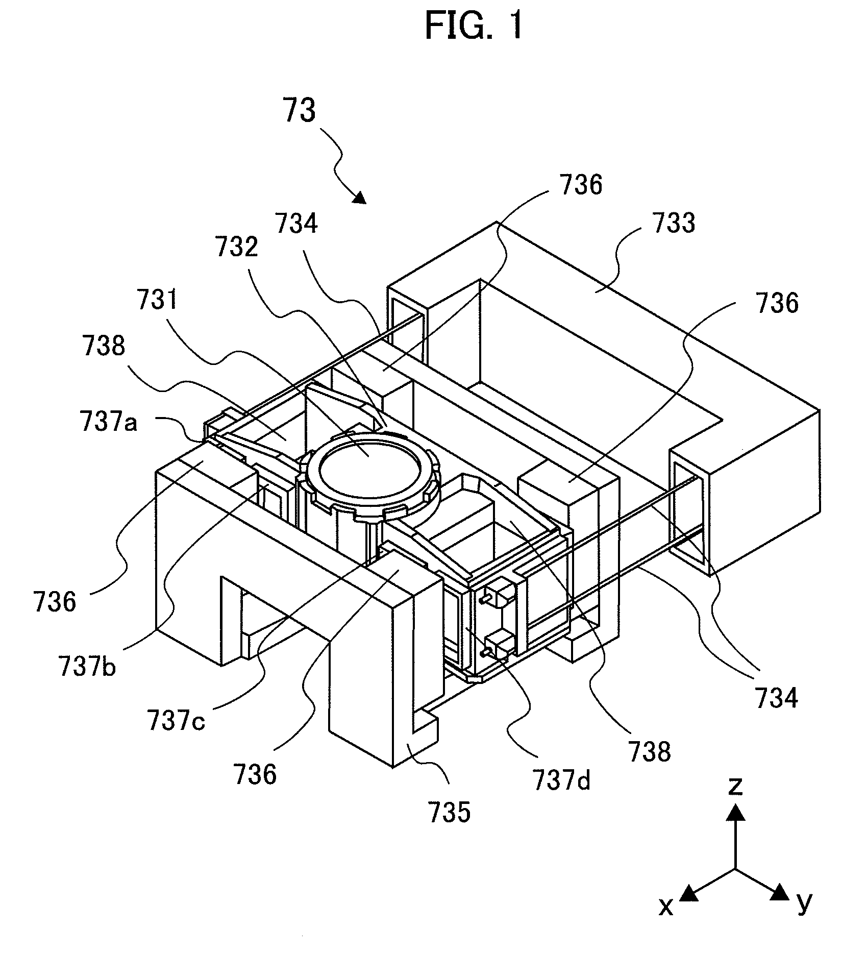
[0033]FIG. 1 is a perspective view of an objective lens actuator 73, according to the present invention.

[0034]In FIG. 1, the “x”-axis direction thereof indicates a jitter direction, i.e., a tangential direction of an optical disc not shown in the figure, the “y”-axis direction thereof a tracking direction, i.e., a radial direction of the optical disc, and “z”-axis direction thereof a focusing direction, i.e., a direction of an optical axis of an objective lens 731, respectively. Also, definitions are made therein, the direction for the objective lens 731 to approach to the optical disc not shown in the figure is “up” while “down” far away from that.

[0035]The objective lens actuator 73 comprises a magnetic circuit, a moving part, onto which the objective lens 731 is attached, a holder 733 for holding this moving part therein, support members 734 for elastically supporting the moving part with respect to the holder 733, a yoke 735, and permanent magnets 736. The wire-like support memb...

embodiment 2

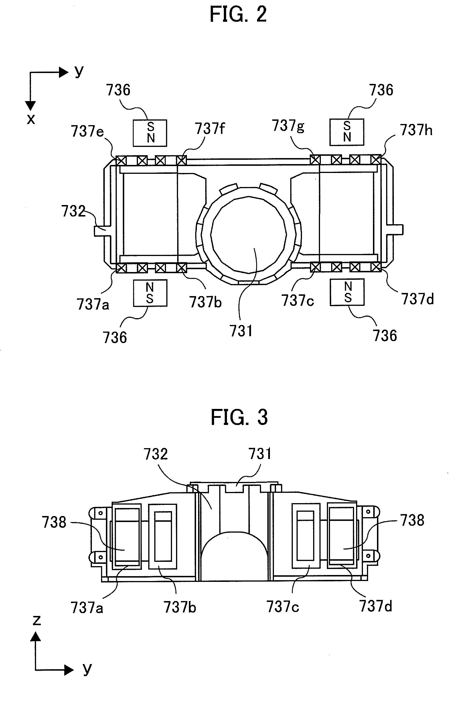
[0061]FIG. 6 is an upper view for showing the moving part and the permanent magnets 736, building up the objective lens actuator 73, according to a second embodiment (i.e., an embodiment 2) of the present invention.

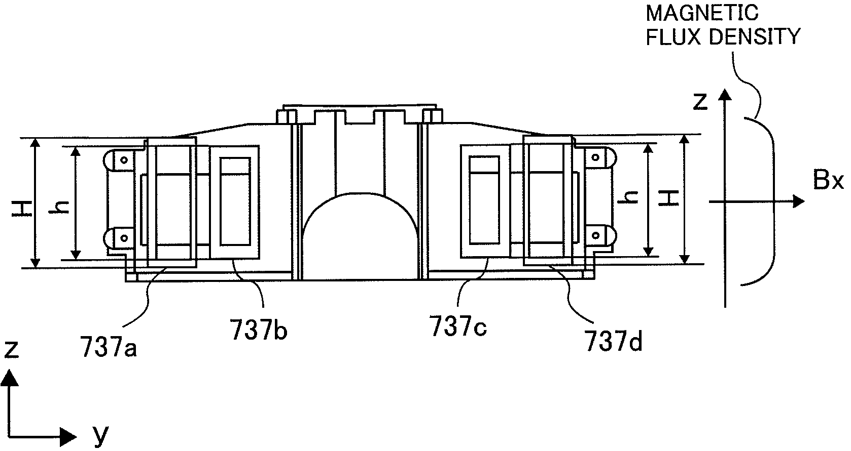
[0062]In FIG. 6, although as the third feature of the embodiment 1 mentioned above lies in that the four (4) pieces of tracking coils are connected in series, wherein the length of the coil wire per one (1) turn is equal to each other among the four (4) pieces of tracking coils, and the number of turns of the outer tracking coils 737a and 737d far from the objective lens 731 among the four (4) pieces of tracking coils 737a to 737d is smaller than the number of turns of the inner tracking coils 737b and 737c near to the objective lens 731 among the four (4) pieces of tracking coils 737a to 737d: however, according to the present embodiment, it is characterized in that the four (4) pieces of tracking coils are connected in series, wherein the length of the coil wire per one...

embodiment 3

[0068]Although as the third feature of the embodiment 1 mentioned above lies in that the four (4) pieces of tracking coils are connected in series, wherein the length of the coil wire per one (1) turn is equal to each other among the four (4) pieces of tracking coils, and the number of turns of the outer tracking coils 737a and 737d far from the objective lens 731 among the four (4) pieces of tracking coils 737a to 737d is smaller than the number of turns of the inner tracking coils 737b and 737c near to the objective lens 731 among the four (4) pieces of tracking coils 737a to 737d: however, according to the present embodiment, it is characterized in that the four (4) pieces of tracking coils are divided into two (2) of an outside and two (2) of an inside, wherein a pair of tracking coils of the outside one or the inside one are connected in parallel, the length of the coil wire per one (1) turn and the number of turns are equal to each other among the four (4) pieces of tacking co...


PUM


Abstract

An objective lens actuator, having a small tilt of an objective lens, for driving the objective lens in a focusing direction and a tracking direction, so as to focus lights on a recording surface of an optical disc, as a recording medium of information, comprises therein: a magnet; a lens holder, which is configured to hold the lens thereon; and four (4) pieces of tracking coils are disposed in a line on a side surface of the lens holder for holding the objective lens thereon, facing to the magnet. And also, an objective lens actuator, having a small tilt of an objective lens, for driving an objective lens in a focusing direction and a tracking direction, so as to focus lights on a recording surface of an optical disc, as a recording medium of information, comprises therein: magnets, which are disposed on two (2) surfaces putting the objective lens therebetween; a lens holder, which is configured to hold the lens thereon; and four (4) pieces of tracking coils are disposed in a line on each of two (2) side surfaces of the lens holder for holding the objective lens thereon, facing to the magnets.

Description

BACKGROUND OF THE INVENTION[0001]The present invention relates to an objective lens actuator to be used in an optical disc apparatus for reproducing or recording information onto or from a recording surface of an optical disc.[0002]In an optical disc apparatus for recording information onto a disc-like information recording medium or reproducing information recording thereon, there is mounted an objective lens actuator for actuating or driving an objective lens in a focusing direction and a tracking direction, so as to record or reproduce the information, correctly, following a tack on the optical disc.[0003]In general, such the objective lens actuator is built up with, a magnetic circuit made of a yoke and a permanent magnet, a moving part attached with an objective lens thereon, a holder for holding this moving part thereon, and a support member for elastically supporting the moving part with respect to the holder. Onto the moving part are attached a focusing coil and a tracking c...

Claims


Application Information

Patent Timeline
Patent Type & Authority Applications(United States)
IPC IPC(8): G02B7/04
CPCG11B7/0935G11B7/0933
Inventor OCHI, MANABUKIMURA, KATSUHIKOYAMADA, SOUICHIROUITOU, TETSUO
Owner HITACHI MEDIA ELECTORONICS CO LTD
Why Eureka
Try Eureka