
Fastener system, fastener system article, and method

a fastener and bolt technology, applied in the direction of threaded fasteners, screws, ways, etc., can solve the problems of bolts being susceptible to inadvertently exiting the bolt hole, bolts may strike and injure a nearby worker, damage nearby machinery, and the bolt may be itself damaged

Active Publication Date: 2009-05-07
REIMLER JAMES L
View PDF41 Cites 40 Cited by
  • Summary
  • Abstract
  • Description
  • Claims
  • Application Information

AI Technical Summary

Benefits of technology

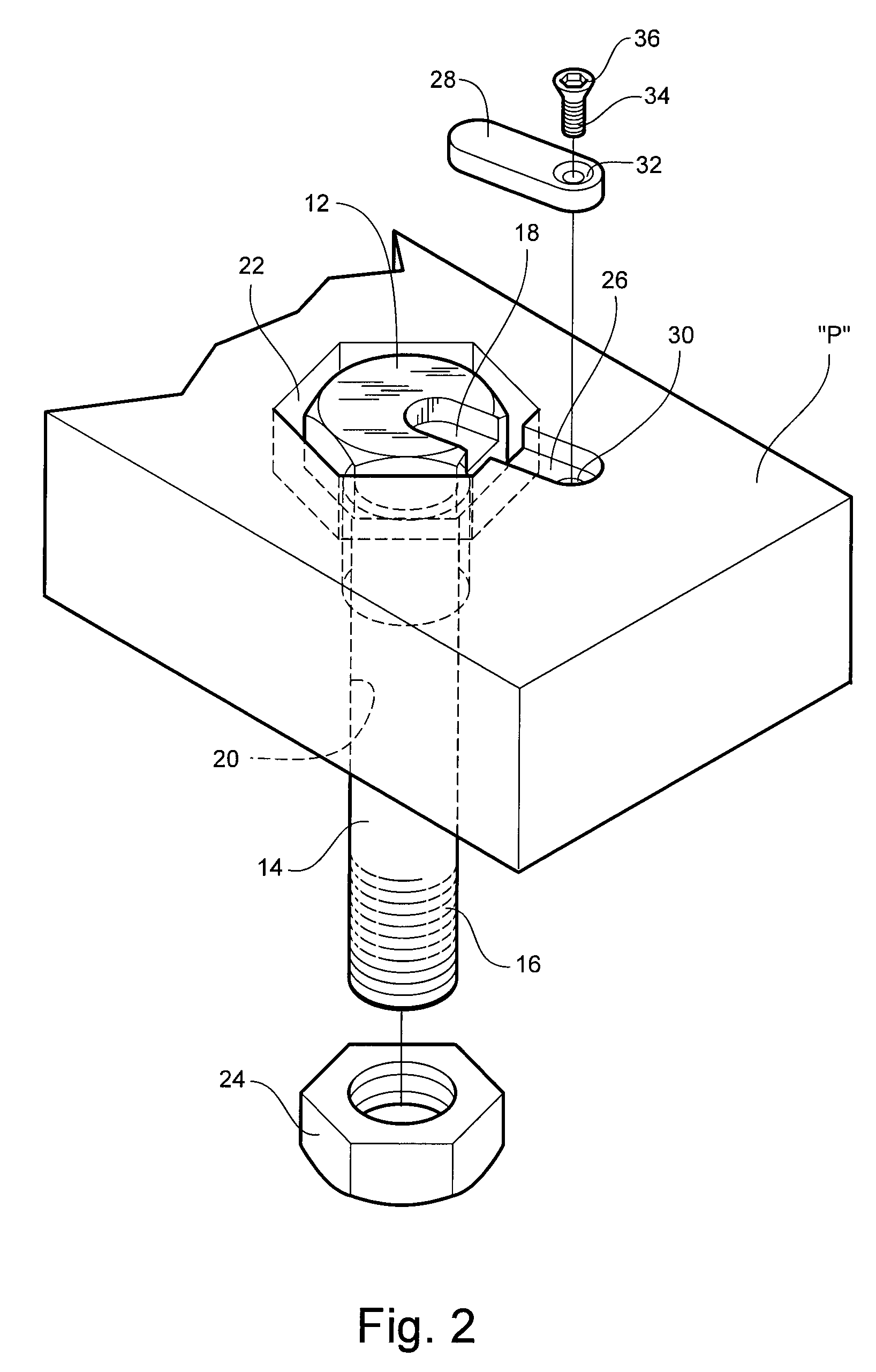
[0037]Preferably, the perimeter of the bar 28 is slightly smaller than the recess 18 in the bolt head 12 so that the looseness of the bolt 10 in the bolt hole 20 and counterbore 22 is maintained. The bolt 10 can be quickly removed by removing the bar 28.
[0043]Referring now to FIG. 8, a variation on the systems shown in FIGS. 4 and 6 is illustrated, where like reference numerals indicate like elements. A small cover 80 is adapted to fit into the counterbore 22 and lie flush or slightly below flush with the surrounding surface of part “B”. A pair of screws 32, 34 extend through screw holes 90, 92 in the cover 30 and are threaded into threaded holes 36, 38 in the counterbore 22. The cover 80 includes on its underside a plurality of downwardly-extending tabs 82, 84, 86, 88 that wedge between the bolt head 13 and the sidewalls of the counterbore 22. The bolt head 13 is therefore captured in the counterbore 22 in a manner similar to that described above, and the bolt 11 is prevented from both rotating and failing from the counterbore 22 when inverted.
[0045]Preferably, the perimeter of the bar 28 is slightly smaller than the perimeter of the adjacent portion of the recess 26 so that the looseness of the bolt head 13 in the counterbore 22 is maintained even though the bolt 11 cannot be removed without first removing the bar 28. The bolt 11 can be quickly removed by removing the bar 28.

Problems solved by technology

When the bolt is captured and retained in the bolt hole by the nut instead of by mating threads on the bolt and the interior of the bolt hole, the bolt is susceptible to inadvertently exiting the bolt hole, either by an impact on the shank along the axis of the bolt, or by the bolt failing out of the bolt hole when the part is inverted.
In such cases, the failing bolt may strike and injure a nearby worker, damage nearby machinery or be itself damaged.

Method used


Image

  • Fastener system, fastener system article, and method
  • Fastener system, fastener system article, and method
  • Fastener system, fastener system article, and method

Examples


Embodiment Construction

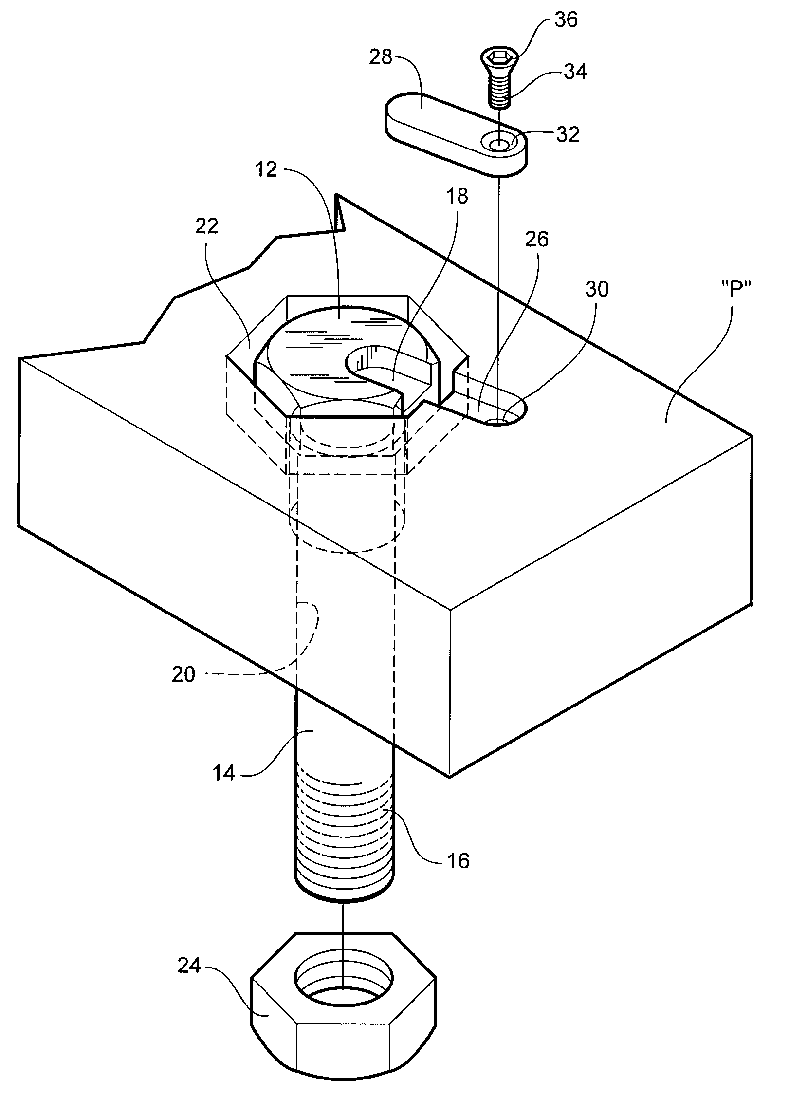
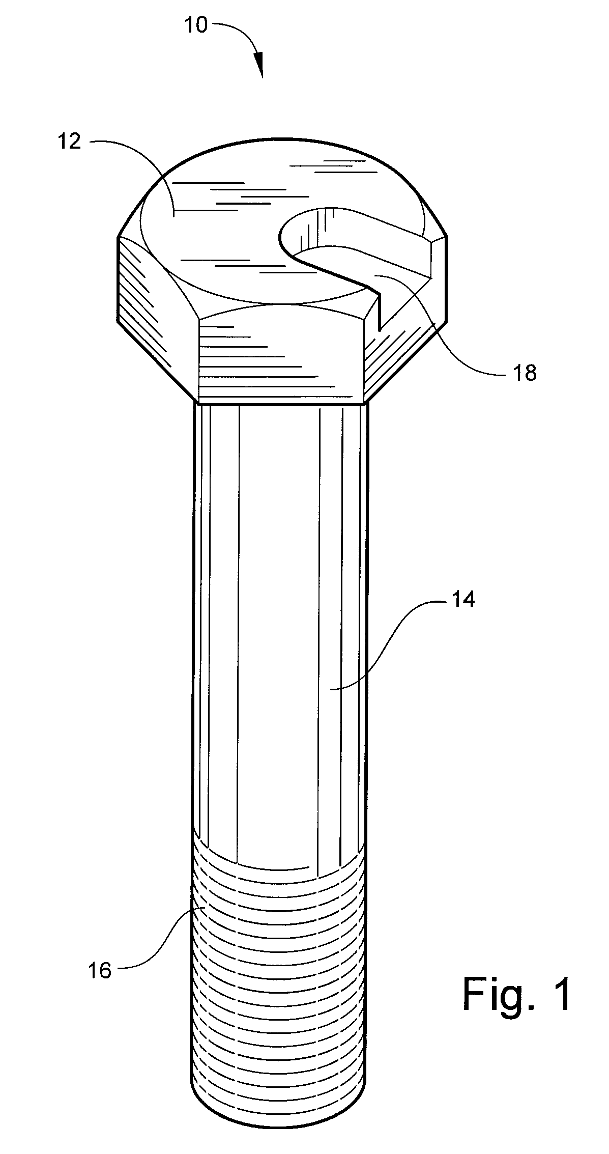
[0035]Referring now specifically to the drawings, a bolt according to the present invention is shown generally in FIG. 1 at reference numeral 10. The bolt 10 includes a bolt head 12, such as a hex head, a threadless shank portion 14 extending outwardly from the head 12, and a distal threaded portion 16. The bolt head 12 also includes a recess 18 that extends to and communicates with the edge of the bolt head 12. This bolt 12 is exemplary of many variations of bolts and other elongate fasteners that have application to this invention. Preferably, the recess 18 does not extend the entire depth of the bolt head 12.

[0036]Referring now to FIGS. 2 and 3, the bolt 10 is shown positioned in an oversized bolt hole 20 and an oversized counterbore 22 in a part “P”. The counterbore 22 is sufficiently large to allow easy removal of the bolt 12 when not captured in the bolt hole 20 by, for example, a nut 24. The bolt head 12 is flush with or slightly below the level of the surrounding surface of ...


PUM


Abstract

A fastener system for retaining a loose elongate fastener in a counterbore, including an elongate fastener, such as a bolt, having a head for being received and retained in a counterbore in a structure and in generally flush relation to a surface of the structure surrounding the counterbore, and a retaining member for being secured to the structure proximate the counterbore and overlapping the counterbore to trap the loose fastener in the counterbore.

Description

TECHNICAL FIELD AND BACKGROUND OF THE INVENTION[0001]This invention relates to a fastener system, fastener system article such as a bolt, and a method of retaining a loose elongate fastener in a counterbore. In many industrial applications large bolts are used to releasably connect machinery parts together. The bolts may be deliberately positioned in holes that are oversized in relation to the diameter of the bolt shank, and with a counterbore that is oversized in relation to the size of the bolt head. This may be done for a number of reasons that include the desire to prevent impact shock applied directly to the bolt through the machine part, to allow easy bolt removal when desired, and to facilitate minute degrees of adjustment to the machine parts before the nut is tightened. In many such cases the counterbore is oversized to a sufficient degree to allow easy removal of the bolt, but is small enough to prevent more than a minimal degree of rotation. For example, with a hex-head b...

Claims


Application Information

Patent Timeline
Patent Type & Authority Applications(United States)
IPC IPC(8): F16B21/00
CPCF16B37/14F16B39/10F16B41/002Y10S411/955Y10T24/44Y10S411/999Y10S411/996Y10T24/44017Y10T24/44026Y10S411/978
Inventor REIMLER, JAMES L.
Owner REIMLER JAMES L
Learn More