Boot with improved tightening of the upper

Inactive Publication Date: 2009-05-14
SALOMON SA
View PDF26 Cites 14 Cited by
  • Summary
  • Abstract
  • Description
  • Claims
  • Application Information

AI Technical Summary

Benefits of technology

[0016]In view of the above, among other features, the invention improves foot support in the boot or, in other words, the i

Problems solved by technology

Consequently, performance, especially in sports, is adversely affected.
Moreover, repeated foot movements in the upper can translate into friction

Method used


Image

  • Boot with improved tightening of the upper
  • Boot with improved tightening of the upper
  • Boot with improved tightening of the upper

Examples


first embodiment

[0037]The first embodiment described hereinafter relates more particularly to boots intended for the practice of cross-country skiing or telemark skiing. However, the invention applies to other fields, such as those mentioned above.

[0038]The first embodiment is described hereinafter with reference to FIGS. 1 to 6.

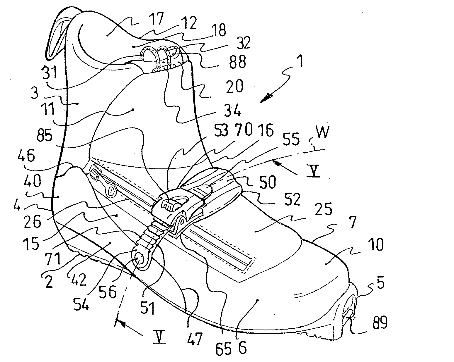
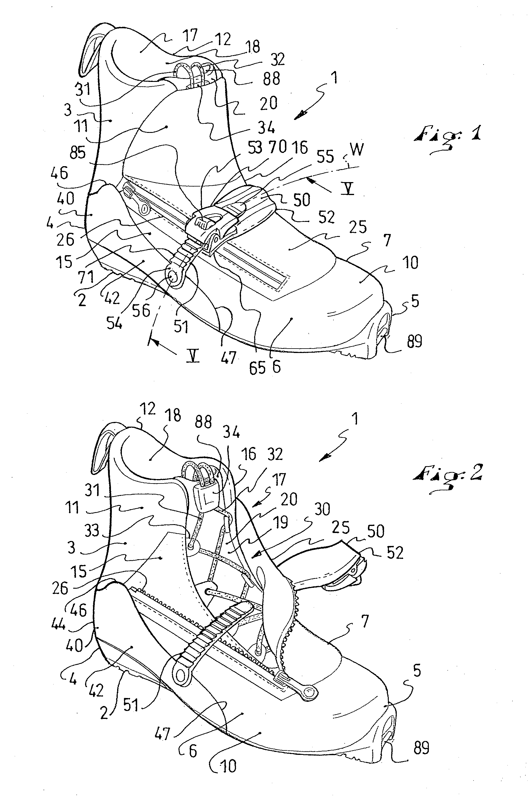
[0039]As shown in FIG. 1, a cross-country ski boot is provided to receive the user's foot.

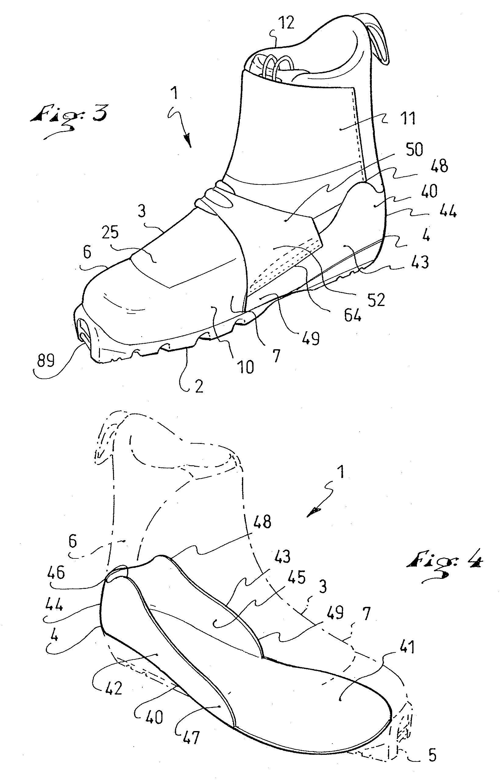
[0040]As known, the boot 1 includes a walking sole 2, or external sole, and an upper 3. The boot 1 extends lengthwise from a rear end 4, or heel, to a front end 5, or tip, and widthwise between a lateral portion 6 and a medial portion 7.

[0041]As shown, the upper 3 includes a lower portion 10, provided to surround the foot, as well as a top portion 11, provided to surround the ankle. Thus, the illustrated boot has a high upper. However, an upper of a boot according to the invention can have only the lower portion, which has a top edge extending below the ankle, i.e., a low upper, or a t...

second embodiment

[0080]The second embodiment, according to FIG. 7, features a boot 1, which includes a sole 2, a lateral portion 6 with a lateral quarter 15, a medial portion7 with a medial quarter 16, and a tongue 20. Also featured is a reinforcement 40, which includes a bottom portion 41, a lateral wall 42 and a medial wall 43. Also found in this embodiment are a transverse linkage 50, with a first portion 51, a second portion 52, and a connecting mechanism 53.

[0081]For the second embodiment of the invention, the first portion 51 is affixed directly to the reinforcement 40, more precisely to the lateral wall 42. Conversely, contrary to the first embodiment, the second portion 52 is affixed to the reinforcement 40 indirectly. In fact, the second portion 52 is affixed to the medial quarter 16 by any suitable expedient, such as an adhesive, welding, stitching, any equivalent means, or a combination of such means. It can be said that the connection of the second portion 52 to the upper 3 is farther fr...

third embodiment

[0082]the invention is described with reference to FIG. 8, in which, once again, the boot 1 includes a sole 2, an upper 3, a lateral portion 6 with a lateral quarter 15, a medial potion 7 with a medial quarter 16, and a reinforcement 40 with a bottom portion 41, a lateral wall 42, and a medial wall 43.

[0083]A feature specific to the third embodiment is the structure of the transverse linkage 100 and its position. The transverse linkage 100 includes a first portion 101, a second portion 102, and a connection 103 for permanent connection of the first portion 101 to the second portion 102. In fact, the portions 101, 102 are permanently connected to one another by the connection 103, shown in the form of an articulation. The connection 103 can include a rivet, a screw, or any equivalent.

[0084]The second portion 102 is permanently affixed to the medial portion 7, as described above for the portions 52. In addition, a ratchet tightening mechanism 110 is permanently affixed to the lateral ...


PUM


Abstract

A boot including a sole and an upper, the boot extending lengthwise from a heel to a front end, widthwise between a lateral portion and a medial portion, and height-wise from the sole to an upper end. The boot includes a reinforcement that is more rigid than the upper, at least in the region of the instep, the reinforcement including a lateral wall and/or a medial wall, and extending beneath the instep, the boot further including a transverse linkage provided to tighten the instep zone, the linkage extending from the lateral portion to the medial portion in a transverse plane of the boot.

Description

CROSS-REFERENCE TO RELATED APPLICATION[0001]This application claims priority under 35 U.S.C. §119 of French Patent Application No. 07 07951, filed on Nov. 13, 2007, the disclosure of which is hereby incorporated by reference thereto in its entirety.BACKGROUND OF THE INVENTION[0002]1. Field of the Invention[0003]The invention relates to an article of footwear, or boot, and, more particularly, to a boot adapted for walking, skiing, sports, and other activities.[0004]Boots of the aforementioned type can be used in fields such as cross-country skiing or telemark skiing, walking or running on flat terrain or in mountainous areas, mountaineering, snowboarding, snowshoeing, roller skating, skateboarding, cycling, ball-playing sports, or the like.[0005]2. Description of Background and Other Information[0006]A boot, in the general sense of the term, can have a low upper, a high upper, or a mid-upper, i.e., an upper that extends above the ankle, one that is below the ankle, or one that extend...

Claims


Application Information

Patent Timeline
IPC IPC(8): A43B5/04
CPCA43B5/0411A43B5/0482A43C11/14A43B5/1625A43B23/16A43B5/0492
Inventor CHOVINO, THIERRYDONNADIEU, THIERRY
Owner SALOMON SA
Why Eureka
Try Eureka