Anti-icing apparatus and method for aero-engine nose cone

a technology of anti-icing apparatus and nose cone, which is applied in the direction of engine fuction, air transportation, turbine/propulsion fuel control, etc., can solve the problem of reducing the thermodynamic performance of gas turbine engines

Inactive Publication Date: 2009-05-14
PRATT & WHITNEY CANADA CORP
View PDF16 Cites 32 Cited by
  • Summary
  • Abstract
  • Description
  • Claims
  • Application Information

AI Technical Summary

Problems solved by technology

While smaller droplets follow the flow around the nose cone into the engine, the larger droplets tend to impact on the cone surface and freeze forming a...

Method used


Image

  • Anti-icing apparatus and method for aero-engine nose cone
  • Anti-icing apparatus and method for aero-engine nose cone
  • Anti-icing apparatus and method for aero-engine nose cone

Examples


Embodiment Construction

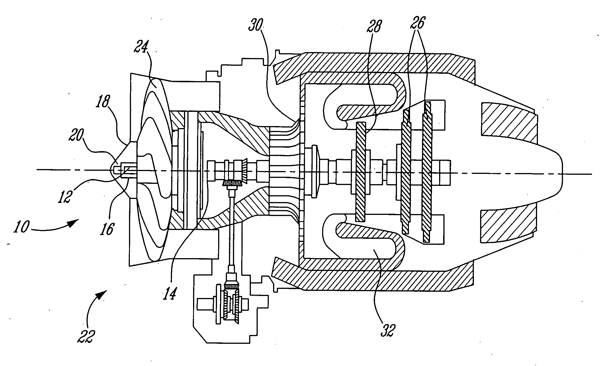
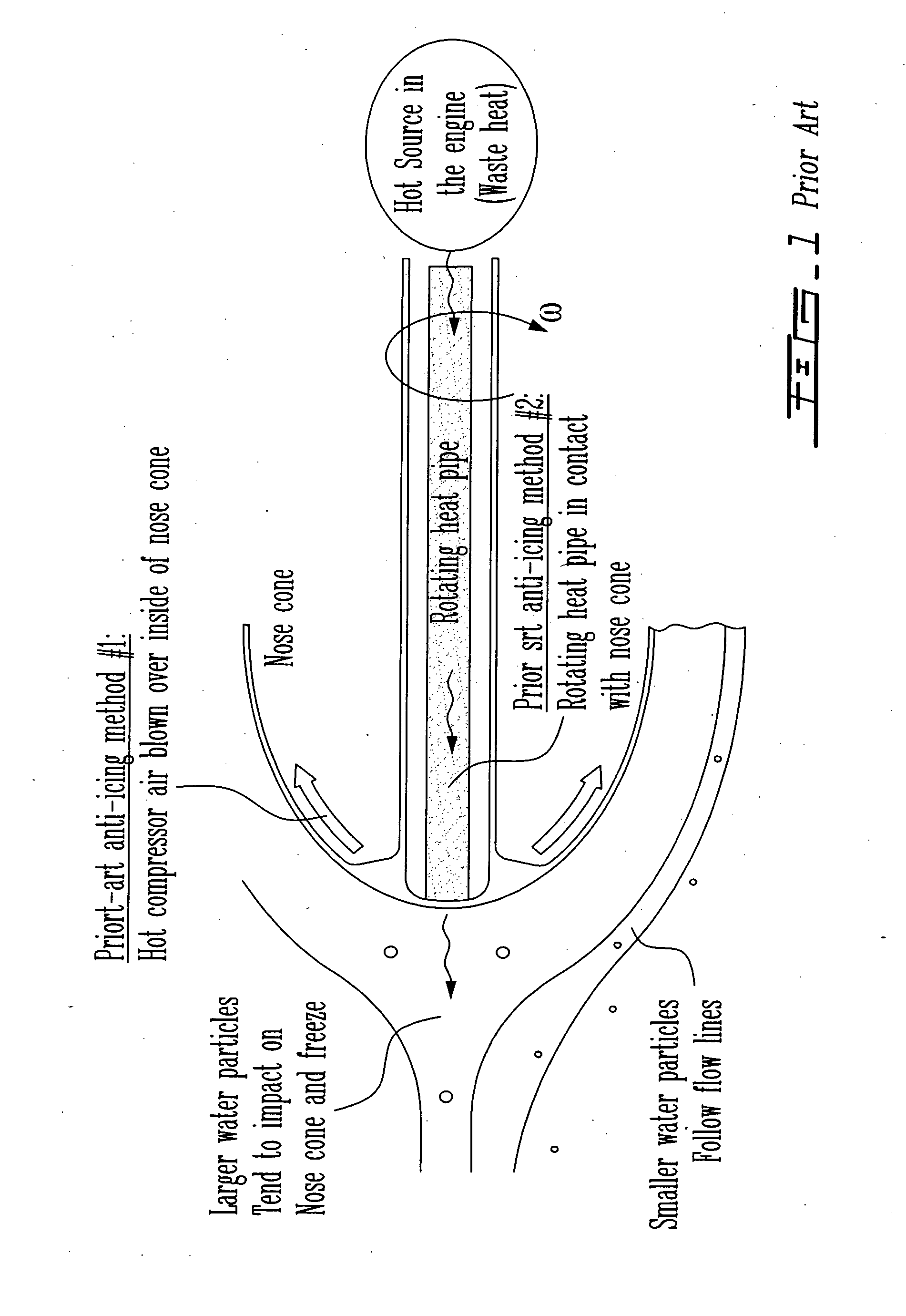
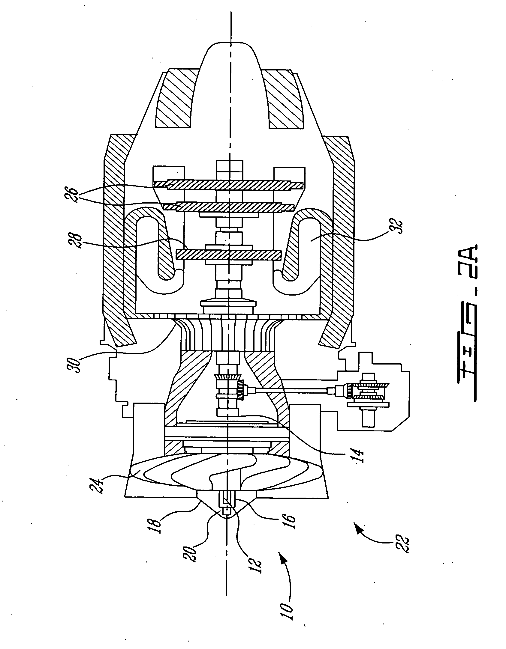
[0023]Referring to FIGS. 2a and 2b, a new aero-engine nose cone anti-icing system 10 using a rotating heat pipe 12 is shown. As will be described in more detail below, the rotating heat pipe 12 transports engine heat, provided to the heat pipe 12 through an evaporator 14, interiorly through an aero-engine central shaft 16 to the engine's nose cone 18 to maintain it above a critical icing temperature, and a condenser apparatus 20 is provided to assist in distributing heat from the heat pipe 12 to the nose cone surface. The aero-engine 22 in this embodiment is a gas turbine turbofan engine, having a fan 24 mounted for rotation on the central shaft 16, the central shaft 16 being driven by a low pressure turbine 26, while a high pressure turbine 28 drives a high pressure compressor 30, both turbines 26, 28 being driven as a result of the combustion of a fuel-air mixture in a suitable combustor 32. Referring to FIG. 1, in use as the aero-engine passes through air with suspended water-vap...


PUM


Abstract

An aero-engine nose cone anti-icing system (10) using a rotating heat pipe (12) is provided to replace the current method of blowing hot compressor bleed air over the nose cone surface. Heat is transferred from a hot source (36) within the engine (22) to the nose cone (18) through a rotating heat pipe (12) along the central shaft (16). A condenser (20) and evaporator (14) are provided which are adapted to the heat transfer requirements and space constraints in the engine (22).

Description

RELATED APPLICATION(S)[0001]This application is a continuation of International Patent Application No. PCT / CA2005 / 000090 filed on Jan. 26, 2005, which claims benefit of Canadian Patent Application No. 2,456,563 filed on Jan. 30, 2004, which are herein incorporated by reference.FIELD OF THE INVENTION[0002]The present invention relates generally to aero-engines and, more particularly, to an anti-icing scheme for an engine nose cone.BACKGROUND[0003]Icing occurs when airplanes move through clouds of suspended water droplets that remain liquid at sub-zero temperatures. While smaller droplets follow the flow around the nose cone into the engine, the larger droplets tend to impact on the cone surface and freeze forming an undesirable layer of ice. Icing is typically prevented on small turbofan engines by blowing hot bleed air from the compressor into and over the nose cone to maintain it above the critical icing temperature. Although this method is effective, increased draw of compressor a...

Claims


Application Information

Patent Timeline
IPC IPC(8): F02G3/00F01D25/02F02C7/047
CPCB64D2033/0233F01D25/02F05D2260/208Y02T50/676F02C7/047Y02T50/60
Inventor BRAND, JOSEPH HORACEDOWHAN, MICHAEL JOHN
Owner PRATT & WHITNEY CANADA CORP
Why Eureka
Try Eureka