Washing machine
- Summary
- Abstract
- Description
- Claims
- Application Information
AI Technical Summary
Benefits of technology
Problems solved by technology
Method used
Image
Examples
first embodiment
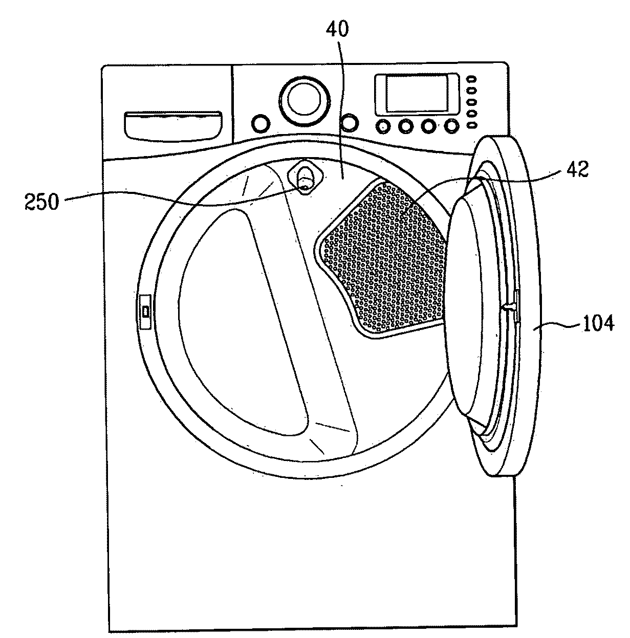
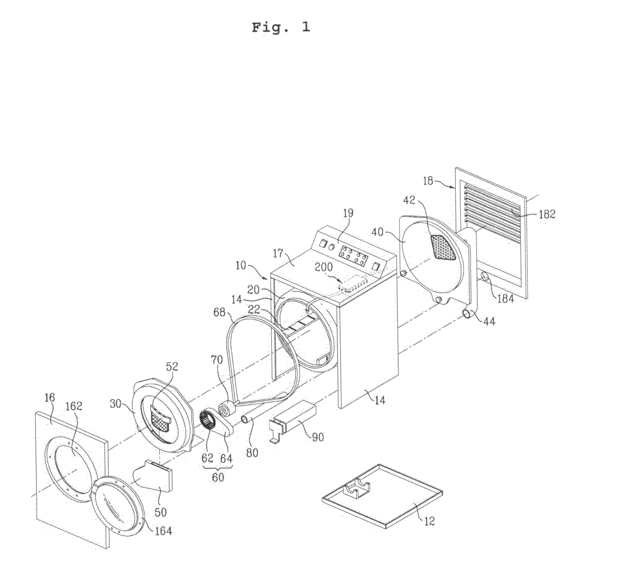
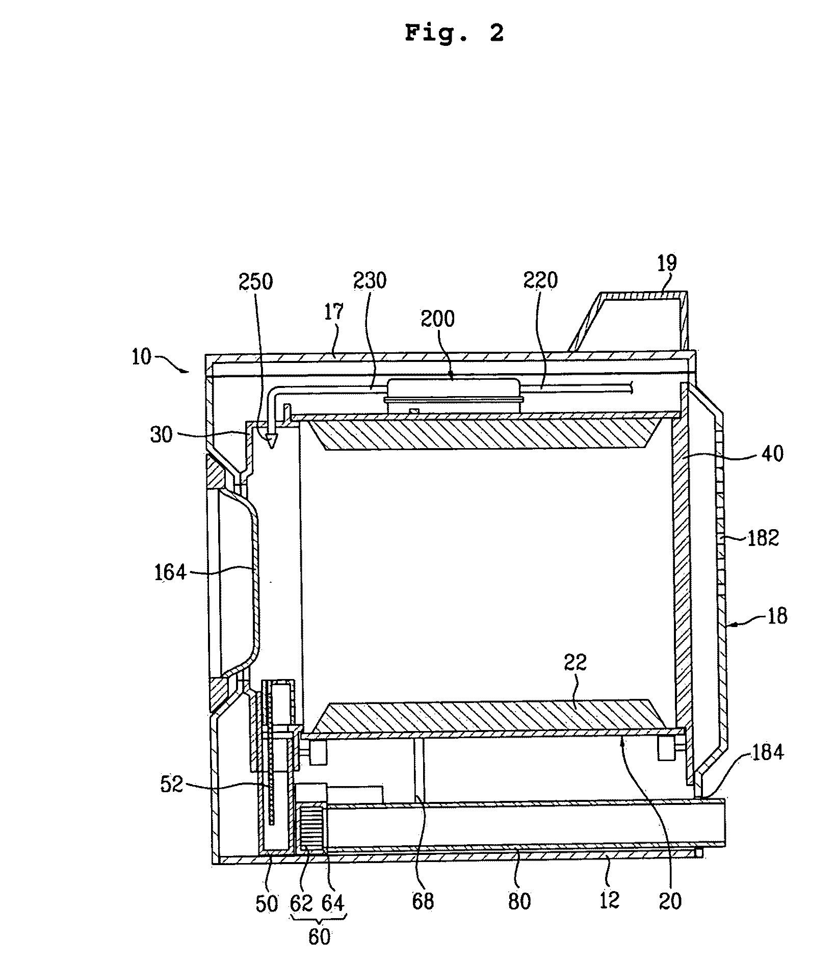
[0062]FIG. 6 is an enlarged perspective view illustrating a state in which a water supply unit 250 according to the present invention is separated from the rear supporter 40.
[0063]Referring to FIG. 6, the water supply unit 250 according to this embodiment includes a nozzle 252 formed with an outlet 254 to spray steam, and a nozzle holder 256 extending from the nozzle 252. The nozzle holder 256 is separably mounted to the rear supporter 40. The nozzle holder 256 may be formed as a member separate from the nozzle 252. In this case, the nozzle holder 256 is connected to the nozzle 252. However, it is preferred that the nozzle holder 256 be integrated with the nozzle 256. In this case, it is possible to more easily mold the water supply unit 250.
[0064]Meanwhile, the nozzle holder 256 is provided with a coupler at a rear surface of the nozzle holder 256, to be separably mounted to the rear supporter 40. That is, in accordance with this embodiment, the coupler is provided at the rear surf...
second embodiment
[0069]FIG. 7 is an exploded perspective view illustrating a state in which a water supply unit 1250 according to the present invention is separated from the rear supporter 40. The water supply unit 1250 is different from that of the previous embodiment, in terms of the structure of the coupling protrusions and the structure of the coupling slots corresponding to respective coupling protrusions. The following description will be given, mainly in conjunction with this difference.
[0070]Referring to FIG. 7, the coupling protrusions 1258 and 1259 according to this embodiment include respective coupling portions 1258a and 1259a each formed at a free end of the corresponding coupling protrusion 1258 or 1259. Preferably, each of the coupling portions 1258a and 1259a has a diameter larger than those of other portions of the corresponding coupling protrusion 1258 or 1259. Meanwhile, it is preferred that the coupling slots 1041 and 1042 include respective reception portions 1041a and 1042a hav...
third embodiment
[0072]FIG. 8 is a front view illustrating a state in which a water supply unit 2000 according to the present invention is mounted to the rear supporter 40. FIG. 9 is a rear perspective view illustrating a state in which the water supply unit 2000 according to the embodiment of FIG. 8 is mounted to the rear supporter 40.
[0073]Referring to FIGS. 8 and 9, the water supply unit 2000 according to this embodiment includes a nozzle 2200 for spraying steam, a front cover 2100 forming a nozzle holder, to which the nozzle 220 is separably mounted, and a ring member 2400 forming a coupler to mount the nozzle 2200 to the front cover 2100.
[0074]Preferably, the front cover 2100 is arranged at an upper portion of the rear supporter 40. In detail, although not shown, the front cover 2100 is fitted in an opening formed through the rear supporter 40.
[0075]Meanwhile, the front cover 2100 has a smooth front surface. An opening 2130 is formed through the front cover 2100 at a lower portion of the front ...
PUM
 Abstract
Description
Claims
Application Information
 - R&D
- Intellectual Property
- Life Sciences
- Materials
- Tech Scout
- Unparalleled Data Quality
- Higher Quality Content
- 60% Fewer Hallucinations
Browse by: Latest US Patents, China's latest patents, Technical Efficacy Thesaurus, Application Domain, Technology Topic, Popular Technical Reports.
© 2025 PatSnap. All rights reserved.Legal|Privacy policy|Modern Slavery Act Transparency Statement|Sitemap|About US| Contact US: help@patsnap.com


