Eureka AIR delivers breakthrough ideas for toughest innovation challenges, trusted by R&D personnel around the world.

Film delivery device and use of same

a technology of film delivery and film, which is applied in the direction of wrapping/bundling articles, external supports, packaging, etc., can solve the problem that the deflecting roller is never able to mov

Active Publication Date: 2009-05-14
M HALOILA
View PDF11 Cites 19 Cited by
  • Summary
  • Abstract
  • Description
  • Claims
  • Application Information

AI Technical Summary

Benefits of technology

[0010]One specific objective of the invention is to disclose a film delivery device which uses S-threading and in which the threading of the film is particularly easy.
[0012]Yet another objective of the invention is to disclose a film delivery device which holds heavy loads and uses S-threading, and is furthermore inexpensive, light-weighted and includes less parts than before.SUMMARY OF THE INVENTION
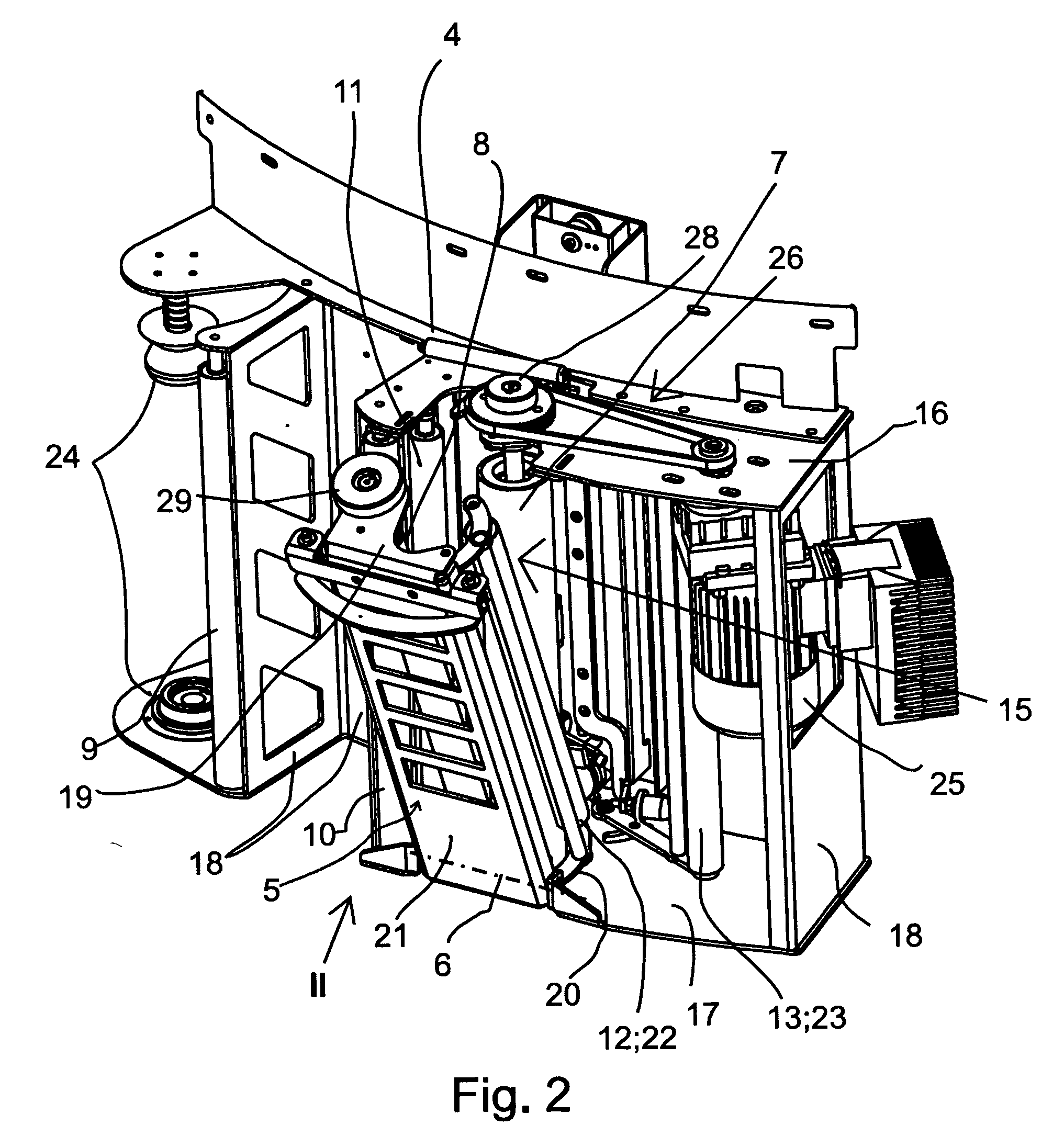
[0015]The invention provides the advantage that it allows the wrapping film to be disposed into the gap from above, which makes the disposition of the film very easy. Threading the film is further facilitated by the fact that in the open position, the first deflecting roller rests against the downstream first prestretch roller and is not able to move to the front side of the first prestretch roller. Therefore, the first deflecting roller is never able to move to a position from which it should be turned against the spring loading, for example manually, to the second position before it would be possible to close the second assembly to the closed position. By the solution according to the invention, it is simple and easy to feed the end of the film when the film is being loaded. In the open position of the second assembly, the end of the film is simply positioned into the fork between the first prestretch roller and the first deflecting roller. The end of the film may be in almost rope-like form. The second assembly is closed, whereupon the film is pressed between the deflecting roller and the first prestretch roller. Then, the prestretch rollers are rotated, so that they draw the film from the rope-like form to an expanded form. A further advantage is that transmission of force to the second prestretch roller in the second opening assembly may be accomplished without providing joints in the rotating axes. In the invention, the advantageous S-threading of the wrapping film is utilized, which provides a larger friction surface than the W-threading on the surface of the prestretch rollers. Whereas normally in the prior art, generating a larger friction surface has meant complex pivoting in order to turn the deflecting rollers behind the prestretch rollers, in the solution according to the invention, on the other hand, pivoting the deflecting roller which contacts the prestretch roller has been made easy by utilizing the path of the opening movement of the second opening assembly in the setting and final positioning of the deflecting rollers.

Problems solved by technology

Therefore, the first deflecting roller is never able to move to a position from which it should be turned against the spring loading, for example manually, to the second position before it would be possible to close the second assembly to the closed position.

Method used


Image

  • Film delivery device and use of same
  • Film delivery device and use of same
  • Film delivery device and use of same

Examples


Embodiment Construction

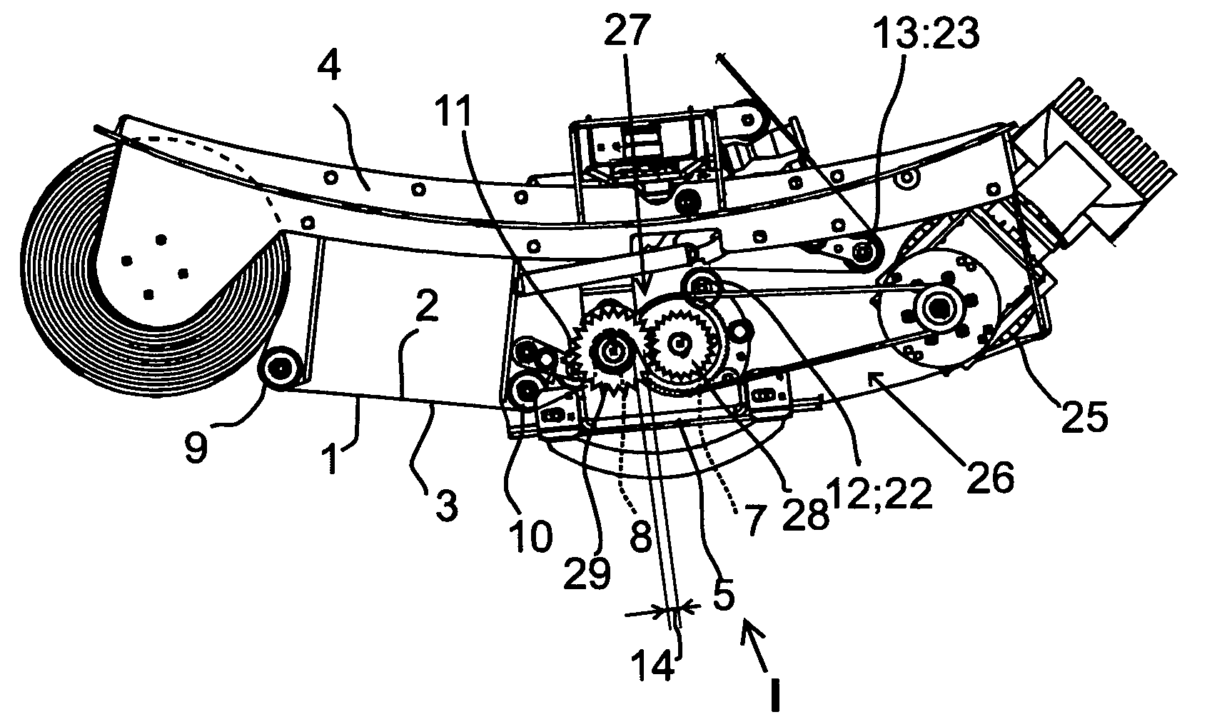
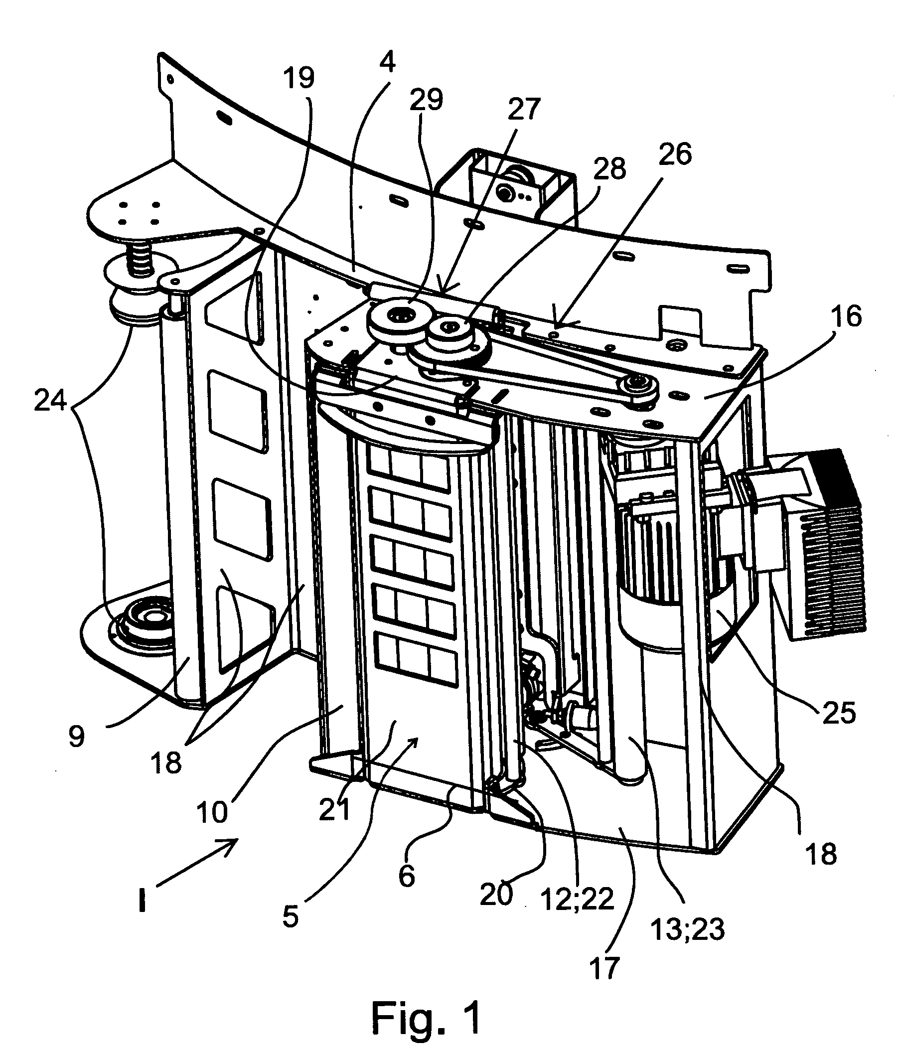
[0033]FIG. 1 to 3 show a film delivery device for a wrapping machine (not shown) for delivering a wrapping film 1 around an article to be wrapped up. FIG. 3 shows that the wrapping film 1 has a first face 2 and a second face 3.

[0034]The film delivery device comprises a first assembly 4 which can be connected to the wrapping machine. The wrapping machine in which the presented film delivery device can be used may be any wrapping machine of the known type, such as[0035]a rotating-arm-type wrapping machine in which the film delivery device is connected to a rotating arm for rotating the film delivery device relative to a stationary article to be wrapped up,[0036]a ring-type wrapping machine in which the film delivery device is connected to a wrapping ring for rotating the film delivery device relative to a stationary article to be wrapped up, or[0037]a column-type wrapping machine in which the film delivery device is connected to a stationary column and the article to be wrapped up is ...


PUM

PropertyMeasurementUnit
speedaaaaaaaaaa
distanceaaaaaaaaaa
lengthaaaaaaaaaa

Abstract

A film delivery device comprising a first assembly (4) which can be connected to a wrapping machine and a second assembly (5) which is pivoted to turn, relative to the first assembly (4), about a horizontal hinge axis (6) between a closed position (I) and an open position (II). A first prestretch roller (7) is in the first assembly (4). A second prestretch roller (8) is in the second assembly (5). The film can be threaded by S-threading between the prestretch rollers (7, 8). The second assembly (5) is hinged at the lower end to the lower end of the first assembly (4) to turn about said horizontal hinge axis (6). The second assembly (5) comprises a pivoted and spring-loaded first deflecting roller (22) which is arranged downstream relative to the first prestretch roller (7). In the open position (II) of the second assembly (5), that part of the first deflecting roller (22) which is close to the lower end thereof is resting against the surface of the first prestretch roller (7).

Description

FIELD OF THE INVENTION[0001]The invention relates to a film delivery device as defined in the preamble of claim 1.BACKGROUND OF THE INVENTION[0002]Previously known from publication U.S. Pat. No. 6,082,081, is a film delivery device for a wrapping machine for delivering a wrapping film around an article to be wrapped up. The film delivery device comprises a first assembly which can be connected to the wrapping machine. Further, the film delivery device comprises a second assembly which is pivoted at the upper end to the upper end of the first assembly to turn about a horizontal hinge axis between a closed position and an open position.[0003]The film delivery device also comprises a prestretch device comprised of two prestretch rollers. It comprises a first prestretch roller which is arranged to the first assembly in substantially vertical direction and arranged to be rotated at a first peripheral speed. Further, the film delivery device comprises a second prestretch roller which is a...

Claims


Application Information

Patent Timeline
Patent Type & Authority Applications(United States)
IPC IPC(8): B65B13/10
CPCB65B11/025B65B11/045B65B2210/20B65B2011/002B65B2210/18B65B41/16
Inventor KOSKELA, JANNE
Owner M HALOILA
Why Eureka
Eureka Blog
Learn More