Flywheel Assembly

a technology of flywheel and assembly, which is applied in the direction of mechanical equipment, machines/engines, and gearboxes, etc., can solve the problems of high-speed rotation of the engine producing vibration, vibration or noise is often undesirable or otherwise objectionable, and damping mechanisms are inadequate, so as to reduce and/or eliminate axial vibration of the flywheel, reduce and/or eliminate torsional vibration

Active Publication Date: 2009-05-14
KOHLER CO
View PDF13 Cites 13 Cited by
  • Summary
  • Abstract
  • Description
  • Claims
  • Application Information

AI Technical Summary

Benefits of technology

[0006]In one aspect, the present invention relates to a flywheel having a flywheel body for rotational association with a crankshaft of an internal combustion engine. The flywheel body includes an inner hub portion and an outer rim portion. In addition, the flywheel body includes a plurality of support ribs extending from the inner hub portion to the outer rim portion. The plurality of support ribs additionally reduces and / or eliminates the axial vibrations of the flywheel, which is a main mode of noise radiation from the flywheel. A conduit, for reducing and / or eliminating torsional vibrations, and formed in the flywheel body between or substantially between the support ribs is also provided.
[0009]In still another aspect, the present invention provides a method of reducing and / or eliminating vibrations of the flywheel. The method comprises providing a flywheel in rotational association with a crankshaft of an internal combustion engine, wherein the flywheel includes a flywheel body having a plurality of support ribs integrally formed therewithin. The method further comprises rotating the flywheel about the axis of the crankshaft such that the plurality of support ribs reduces or eliminates the axial vibrations of the flywheel, which is a main mode of noise radiation from the flywheel.

Problems solved by technology

Often times, high speed rotation of the engine produce vibrations that can propagate through the crankshaft and out to the flywheel assembly and be radiated as a component of the engine noise.
Such vibrations or noises are often undesirable or otherwise objectionable.
Although adequate in most regards, such damping mechanisms are nevertheless inadequate in at least some circumstances.
For example, damping mechanisms connected at least indirectly to the flywheel can add to the overall weight of the flywheel, making the flywheel less desirable for internal combustion engines used in applications requiring portability or otherwise having weight restrictions.
Additionally, external damping mechanisms are susceptible to damage and break-down, rendering the damping mechanism and the flywheel to which it is connected, inefficient or possibly even completely incapable of being used.

Method used


Image

  • Flywheel Assembly
  • Flywheel Assembly
  • Flywheel Assembly

Examples


Embodiment Construction

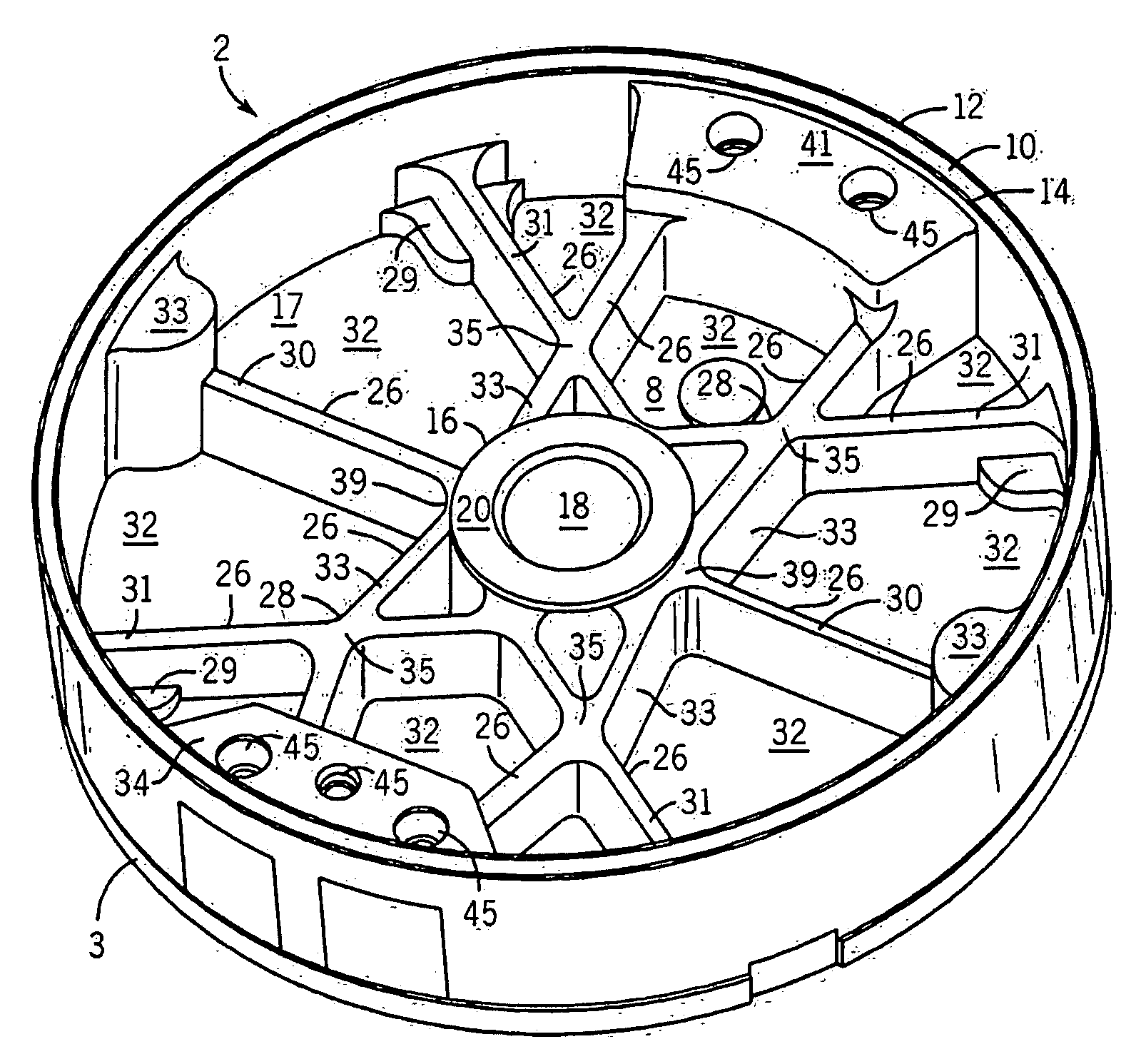
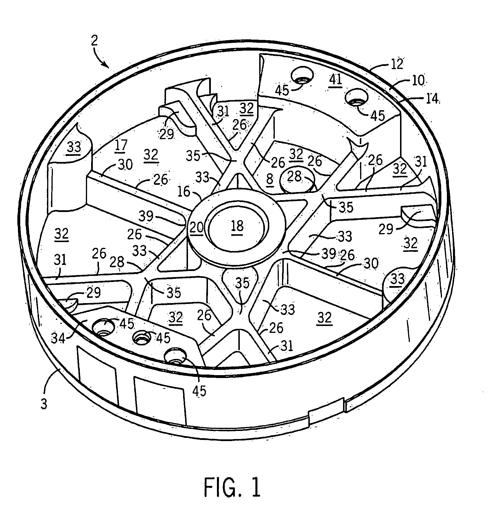
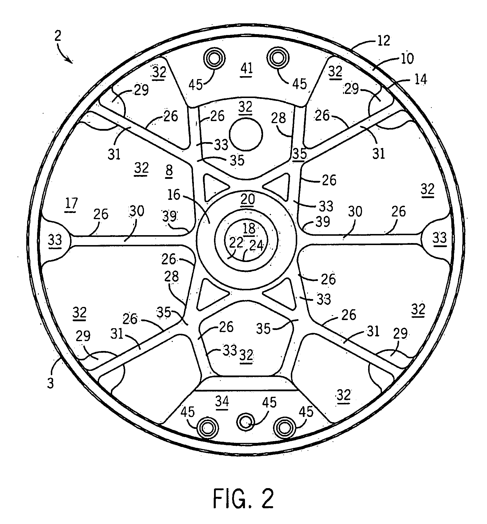
[0024]Referring to FIGS. 1 and 2, top perspective and top views, respectively, of an underside surface of an exemplary flywheel 2, are shown in accordance with at least some embodiments of the present invention. In at least some embodiments of the present invention, the flywheel 2 is intended for use in conjunction with an internal combustion engine (not shown). In particular, the internal combustion engine can be any of a wide variety of engines. For example, some embodiments of the present invention can be employed in conjunction with SORE engines including Class 1 and Class 2 small off-road engines such as those implemented in various machinery and vehicles, including, for example, lawn mowers, snow mobiles and the like. Indeed, in at least some such embodiments, the present invention is intended to be applicable to “non-road engines” as defined in 40 C.F.R. §90.3, which states in pertinent part as follows: “Non-road engine means . . . any internal combustion engine: (i) in or on...


PUM


Abstract

A system for a flywheel assembly for use in conjunction with an internal combustion engine is disclosed. The flywheel assembly includes a flywheel in rotational association with a crankshaft of the internal combustion engine. The flywheel assembly further includes a cooling fan mounted over the flywheel, and capable of rotation therewith. The cooling fan and the flywheel are secured in a constant axial position relative to the crankshaft by virtue of a drive-cup and a retaining nut. Further, the flywheel includes a plurality of integrally formed, intersecting support ribs, for providing excellent dynamic stiffening (e.g., damping) capabilities to the flywheel assembly for substantially reducing and / or eliminating radiated noise.

Description

CROSS-REFERENCE TO RELATED APPLICATIONS[0001]This application claims the benefit of U.S. provisional patent application No. 60 / 999,451 entitled “flywheel assembly” filed on Oct. 18, 2007, the entirety of which is hereby incorporated by reference herein.FIELD OF THE INVENTION[0002]The present invention relates to a flywheel assembly and, more particularly, to a flywheel assembly used in conjunction with a crankshaft of an internal combustion engine.BACKGROUND OF THE INVENTION[0003]Flywheel assemblies are used in a wide variety of applications including, for example, satellite pointing operations, automobiles, telecommunication industry and even some electrification systems. Frequently, flywheel assemblies are mounted for rotation on a crankshaft of an internal combustion engine. Often times, high speed rotation of the engine produce vibrations that can propagate through the crankshaft and out to the flywheel assembly and be radiated as a component of the engine noise. Such vibrations...

Claims


Application Information

Patent Timeline
Patent Type & Authority Applications(United States)
IPC IPC(8): F16H33/02F01P7/02F16C15/00
CPCF16F15/315Y10T74/2121Y10T74/2132
Inventor DOPKE, RUSSELL J.ALBERT, ROGER W.BYKOWSKI, JONATHAN T.UEBELHER, EDWARD A.
Owner KOHLER CO
Why Eureka
Try Eureka