Standpipe direct float valve

a technology of direct float valve and standpipe, which is applied in the direction of valve operation/release device, water supply installation, transportation and packaging, etc., can solve problems such as complex systems, and achieve the effect of constant fluid level

Inactive Publication Date: 2009-05-14
BERMAD CS LTD
View PDF32 Cites 24 Cited by
  • Summary
  • Abstract
  • Description
  • Claims
  • Application Information

AI Technical Summary

Benefits of technology

[0022]There is also provided according to the teachings of the present invention, a method for maintaining a substantially constant flow pressure through an outlet port of a standpipe float valve having a standpipe housing configured with an inlet port and an outlet port, the method comprising: a) providing a valve plug deployed within the standpipe housing, the valve plug configured regulate a flow of fluid into the standpipe housing, and a float element deployed within the standpipe housing and reactive to a fluid level in the standpipe housing, the float element attached to the valve plug and configured to actuate the valve plug; b) provide a flow of fluid to the inlet port; and c) maintain a substantially constant fluid level in the standpipe housing by displacement of the float element in response to a fluid level in the standpipe housing so as to actuate the valve plug between an open position, in which fluid flows through the inlet port into the standpipe housing and a closed position in which fluid flow through the inlet port is blocked.

Problems solved by technology

These system are complex and include numerous component such as a standpipe, a main flow control valve, a control system configure to regulate the operation of the main flow control valve and a float mechanism to actuate the control system.

Method used


Image

  • Standpipe direct float valve
  • Standpipe direct float valve
  • Standpipe direct float valve

Examples


Embodiment Construction

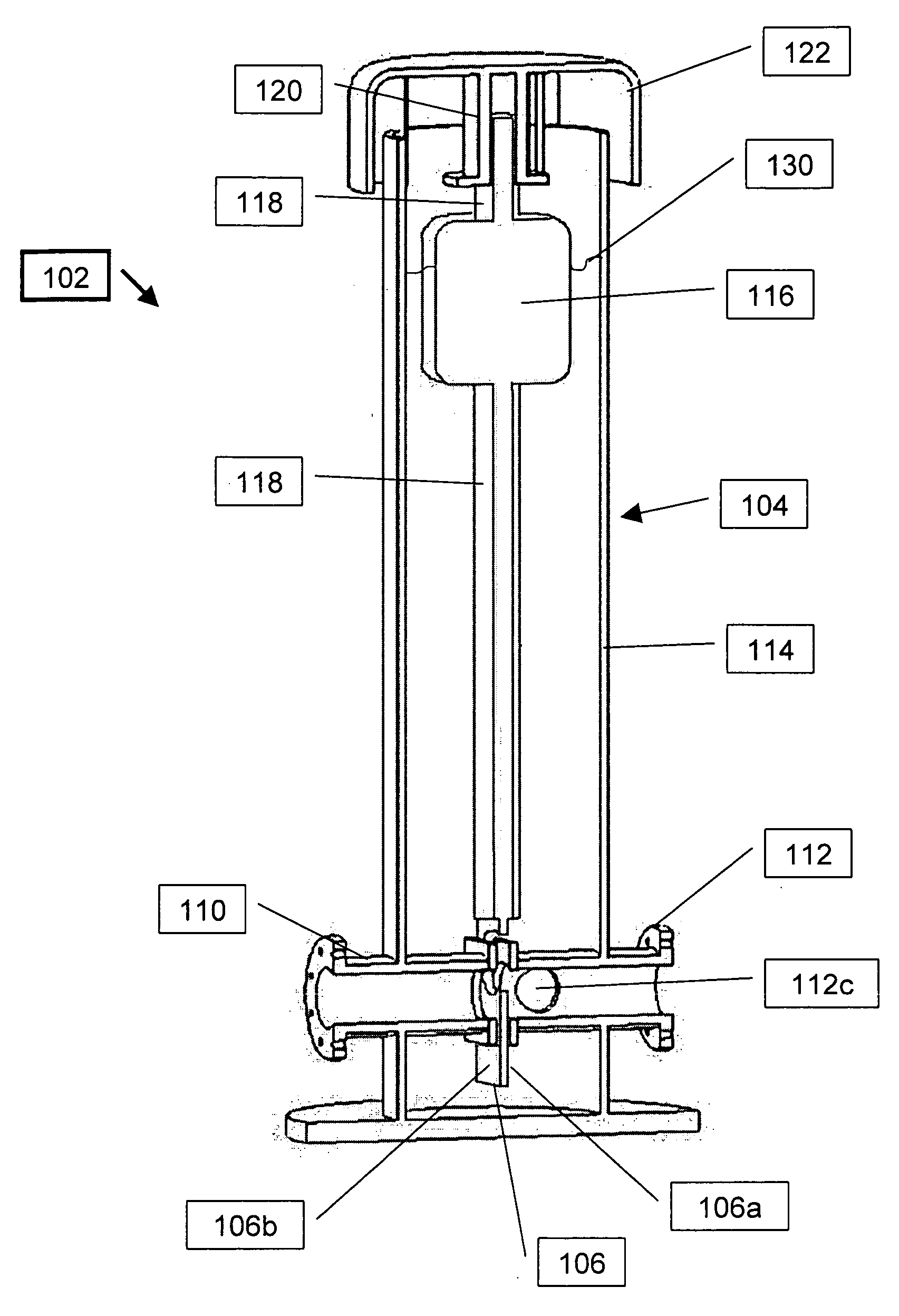
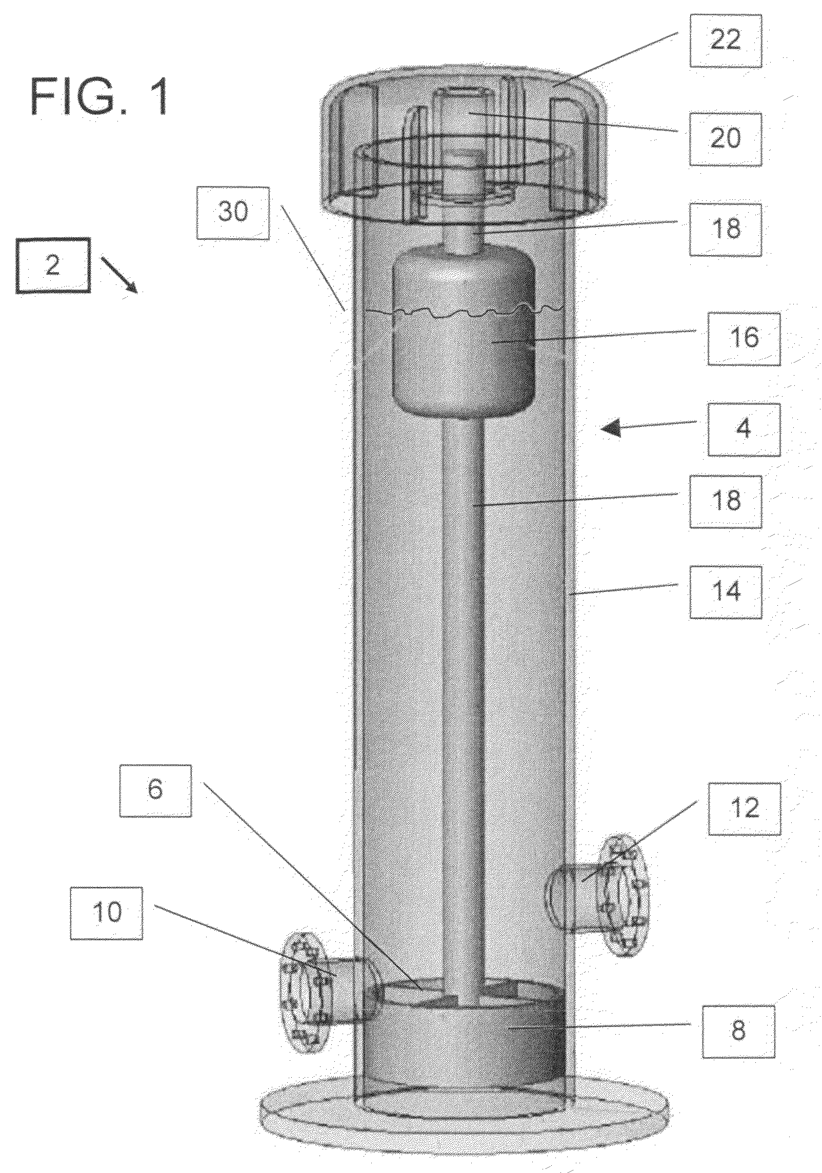
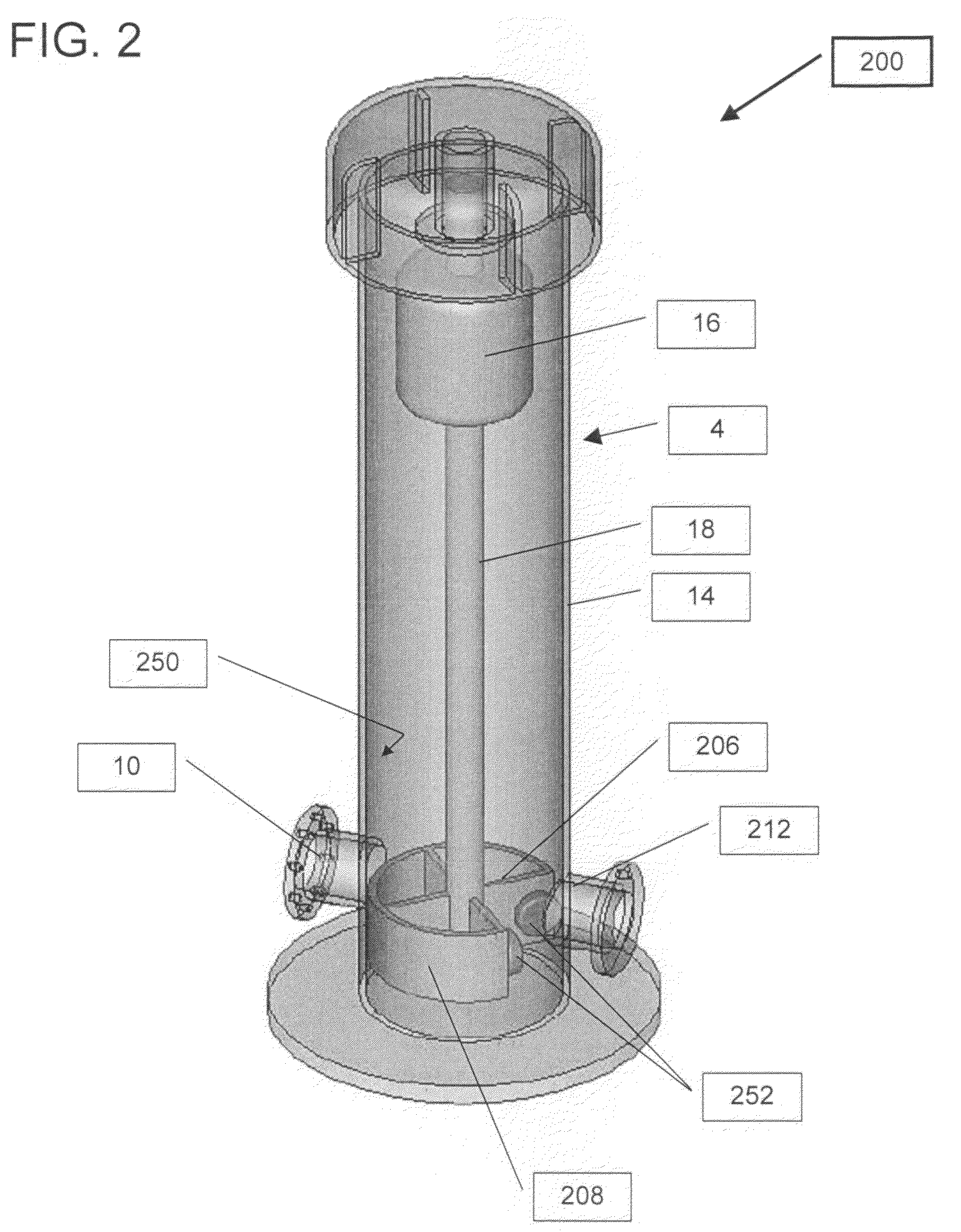
[0035]The present invention is a standpipe float valve in which the float mechanism directly actuates a valve plug that is deployed within the standpipe

[0036]The principles and operation of standpipe float valve according to the present invention may be better understood with reference to the drawings and the accompanying description.

[0037]By way of introduction, the standpipe direct float valve of the present invention is configured such that the valve plug is directly connected to the float element and both the valve plug and the float element are deployed within the standpipe housing.

[0038]In the preferred embodiments described herein, the standpipe housing has an inlet port and at least one outlet port. The valve plug is configured to regulate the fluid level, commonly referred to in the art as head, in the standpipe housing by controlling the flow of fluid through the inlet port and into the standpipe housing. The valve plug is deployed within the standpipe housing and is direc...


PUM


Abstract

The standpipe direct float valve of the present invention is configured such that the valve plug is directly connected to the float element and both the valve plug and the float element are deployed within the standpipe housing. The standpipe housing has an inlet port and at least one outlet port. The valve plug is configured to regulate the fluid level, commonly referred to in the art as head, in the standpipe housing by controlling the flow of fluid through the inlet port and into the standpipe housing. The valve plug is deployed within the standpipe housing and is directly connected to, and actuated by, a float element that is deployed within the standpipe housing and reactive to the fluid level in the standpipe housing. Preferably, the valve plug and the float element are integrally formed. So configure, the standpipe float valve of the present invention provides a method for maintaining a substantially constant flow pressure through an outlet port of a standpipe float valve having a standpipe housing configured with an inlet port and an outlet port. This is accomplished by maintaining a substantially constant fluid level into the standpipe housing by displacement of the float element in response to the fluid level in the standpipe housing so as to actuate the valve plug between an open position, in which fluid flows through the inlet port into the standpipe housing and a closed position in which fluid flow through the inlet port is blocked. A full range of fluid flow through the inlet port and into the standpipe housing is possible due to the fill range of movement of the valve plug between filly closed and fully open is possible.

Description

FIELD AND BACKGROUND OF THE INVENTION[0001]The present invention relates to standpipe float valves and, in particular, it concerns a standpipe float valve in which the float mechanism directly actuates a valve plug that is deployed within the standpipe.[0002]It is known to provide water systems having a standpipe to ensure that the system pressure does not exceed the design pressure for the piping within the system.[0003]The standpipe typically is located upstream of the irrigation system on a ‘T’ off the main supply pipe. Should the pressure of the water entering the standpipe rise above the design value, the water level in the standpipe will rise and overflow the standpipe, spilling out of the open top of the standpipe, thereby protecting the system from damage.[0004]Presently the standpipe is associated with an automatic hydraulic float control valves installed upstream to the standpipe. The float valve maintains a constant water level in the standpipe thereby regulating the stan...

Claims


Application Information

Patent Timeline
Patent Type & Authority Applications(United States)
IPC IPC(8): F16K31/18F17D3/00
CPCF16K31/30Y10T137/0324Y10T137/7413Y10T137/7358
Inventor WEINGARTEN, ZVI
Owner BERMAD CS LTD
Why Eureka
Try Eureka