Fuel filter device

a filter device and fuel technology, applied in the direction of filtration separation, lubricant mounting/connection, separation process, etc., can solve the problems of fuel soaking and swollen nylon, increased pressure loss, and decreased mesh size of the filter body, so as to reduce the load on the fuel pump, increase the pressure of the fuel, and reduce the effect of fuel pump load

Inactive Publication Date: 2009-05-14
NIFCO INC
View PDF4 Cites 24 Cited by
  • Summary
  • Abstract
  • Description
  • Claims
  • Application Information

AI Technical Summary

Benefits of technology

[0008]In the first aspect of the invention, the inner layer part is formed of the non-woven cloth made of the olefin resin, so that the inner layer part is not soaked and swollen with fuel. Accordingly, it is possible to maintain a mesh size of the inner layer part, i.e. gaps between mutually intermeshed fibers of the non-woven cloth, at a desired size. As a result, it is possible to prevent the problem in which the mesh becomes smaller over time and a pressure of the fuel increases (greater pressure loss), thereby decreasing load on the fuel pump. Further, it is possible to prevent the problem in which the filter body is easy to get clogged with dust and dirt, and the pressure of the fuel increases, thereby decreasing load on the fuel pump.
[0009]In the first aspect of the invention, the filter device has the outer layer part formed of the woven mesh. Accordingly, even if the lower surface part of the filter body rubs against a lower inner surface of the fuel tank when the lower inner surface of the fuel tank moves inwardly and outwardly (expansion and contraction of the fuel tank) due to a change in an internal pressure of the fuel tank, the inner layer part formed of the non-woven cloth does not directly contact. Accordingly, it is possible to prevent fraying in the non-woven cloth of the inner layer part due to the rubbing.
[0010]According to a second aspect of the invention, in the fuel filter device in the first aspect of the invention, the woven mesh of the outer layer part is made of an olefin resin such as polyethylene and polypropylene. Accordingly, the woven mesh of the outer layer part tends not to be soaked and swollen with the fuel, and it is possible to maintain a mesh size of the woven mesh at a desired size. When the bag-shape filter body is formed, a filter base member formed of the outer layer part and inner layer part is folded over with the inner layer part on the inside, and the folded filter base member is fused. Accordingly, the inner layer part is easily fused and integrated with the outer layer part.
[0011]According to a third aspect of the invention, in the fuel filter device in the second aspect of the invention, one of warp and woof fibers of the woven mesh of the outer layer part is formed of polyethylene, and the other of the warp and woof fibers is formed of polypropylene. The non-woven cloth of the inner layer part is formed of the fiber made of polyethylene or polypropylene. When the bag-shape filter body is formed, the filter base member formed of the outer layer part and inner layer part is folded over with the inner layer part on the inside, and the folded filter base member is fused. Accordingly, the inner layer part is easily fused and integrated with the outer layer part.
[0012]According to a fourth aspect of the invention, in the fuel filter device in the first aspect of the invention, the inner layer part is formed of a non-woven cloth layer formed with spun-bond method and a non-woven cloth layer formed with melt-blown method. In general, a non-woven cloth formed with the melt-blown method has a mesh finer than that of a non-woven cloth made with the spun-bond method. A non-woven cloth formed with the spun-bond method has a fiber with a larger diameter and higher strength. Accordingly, the non-woven cloth layer formed with the melt-blown method captures fine dust and dirt, and the non-woven cloth layer formed with the spun-bond method provides the inner layer part with rigidity, so that it is easy to maintain the shape of the filter body.

Problems solved by technology

Nylon is easily soaked and swollen with fuel.
As a result, a mesh size of the filter body decreases over time.
When the filter body has a smaller mesh size, a pressure of the fuel increases (greater pressure loss), thereby increasing load on the fuel pump.
Further, the filter body is easy to get clogged with dust and dirt, and the like, and the pressure of the fuel increases, thereby increasing load on the fuel pump.

Method used


Image

  • Fuel filter device
  • Fuel filter device
  • Fuel filter device

Examples


Embodiment Construction

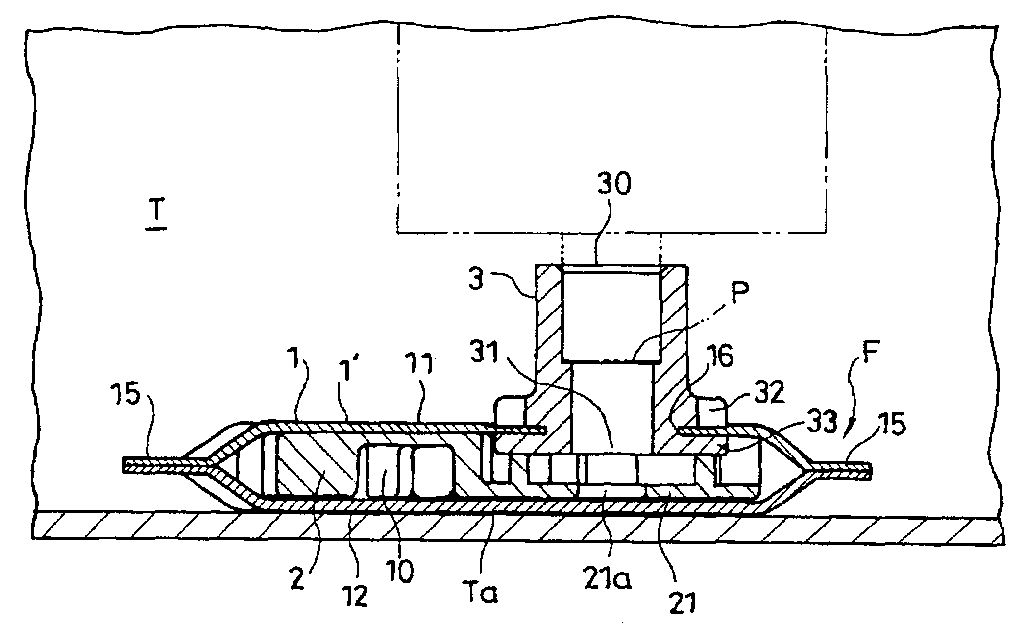
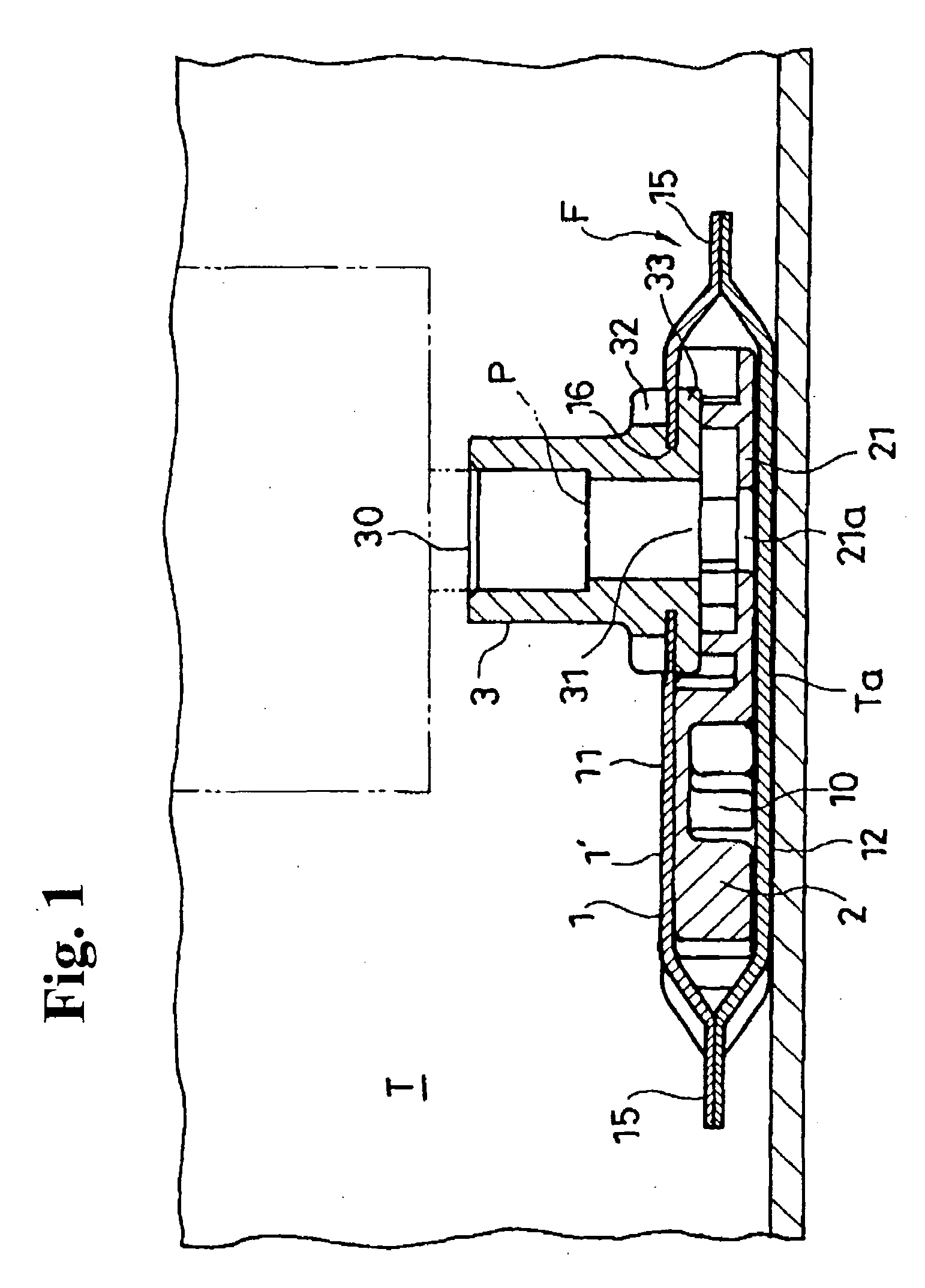
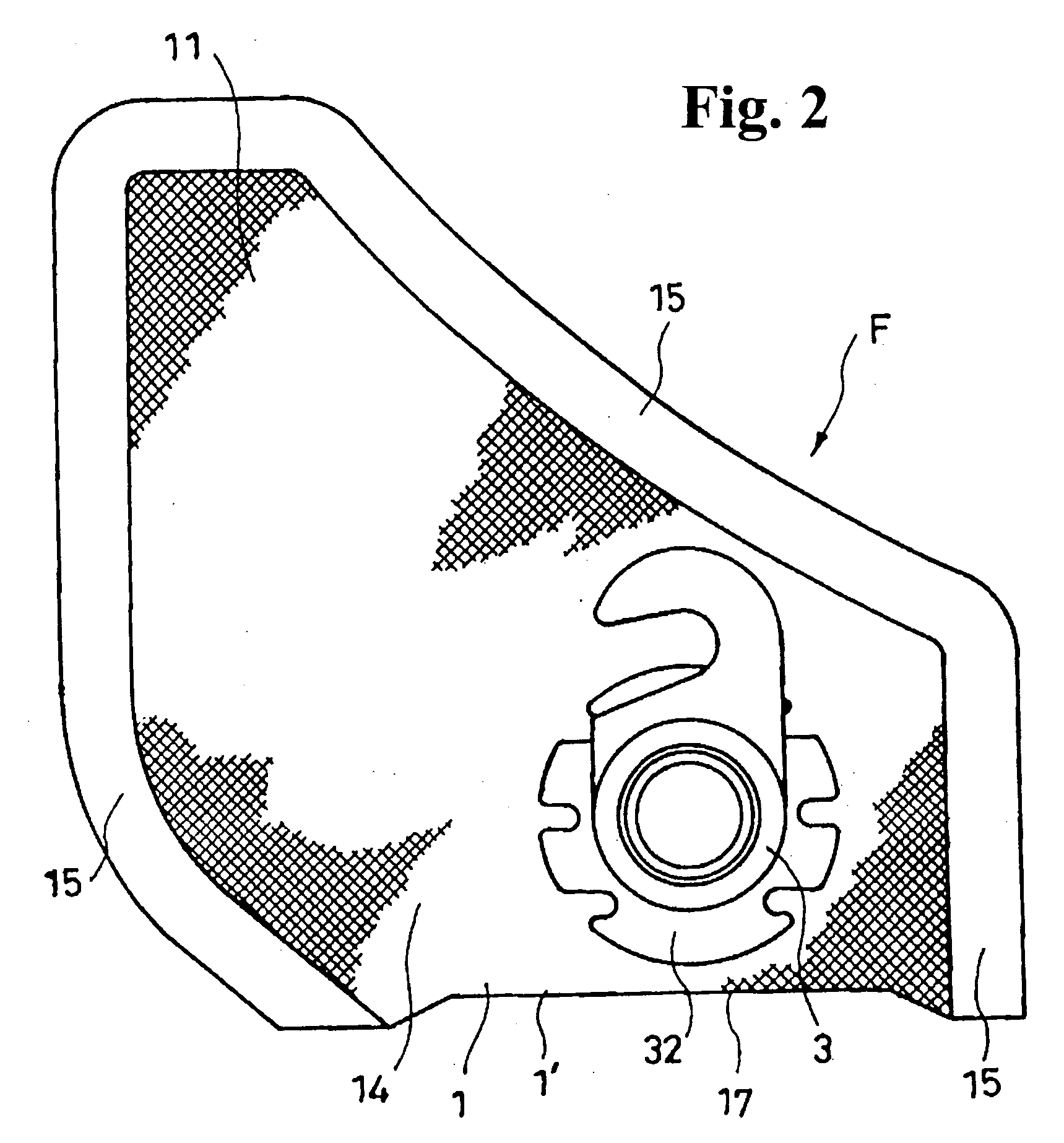
[0025]Hereunder, embodiments of the invention will be explained with reference to the accompanying drawings. FIG. 1 is a schematic view showing a state that a filter device F is installed on a fuel intake port P in a fuel tank T. FIG. 2 is a plan view of the filter device F. FIG. 3 is a side view of the filter device F. FIGS. 4 to 8 are views showing a state that a cylindrical socket body 3 is integrated with an expanded filter base member 1′ before forming a filter body 1 constituting the filter device F. FIGS. 9 to 11 are views showing a space forming member 2 housed inside the filter body 1 for maintaining the filter body 1 in an expanded shape in a state that the filter base member 1′ is integrally provided with the cylindrical socket body 3 and the filter base member 1′ is formed in a bag-shape. FIG. 12 is a sectional view showing an example of a structure of the filter body 1.

[0026]In the embodiment, the fuel filter device F is installed inside the fuel tank T of an automobile...


PUM

PropertyMeasurementUnit
sizeaaaaaaaaaa
mesh sizeaaaaaaaaaa
shapeaaaaaaaaaa

Abstract

A fuel filter device includes a bag-shape filter body and a space forming member disposed in the filter body. The filter body includes an upper surface part, and a lower surface part welded with the upper surface part at edges to form a bag shape. At least the lower surface part has a woven mesh outer layer part, a first inner layer part situated adjacent to the outer layer part and formed of a melt blown non-woven cloth, and a second inner layer part situated adjacent to the first inner layer part at a side opposite to the outer layer part. The second inner layer part is formed of a spun-bonded non-woven cloth. The upper surface part and the lower surface part are all made of polypropylene that is not soaked and swollen with fuel to thereby maintain a mesh size of the filter body without change.

Description

CROSS-REFERENCE TO RELATED APPLICATION[0001]This is a continuation application of Ser. No. 10 / 834,882 filed on Apr. 30, 2004.BACKGROUND OF THE INVENTION AND RELATED ART STATEMENT[0002]The present invention relates to a fuel filter device to be installed on a fuel intake port inside a fuel tank.[0003]Fuel inside a fuel tank is sent to an internal combustion engine through an intake pipe or the like disposed inside the fuel tank. A filter device is installed inside a fuel intake port of the intake pipe in order to remove water and / or a foreign material from the fuel not to be sent into a fuel pump. Japanese Patent Publication (Kokai) No. 07-148405 and Japanese Patent Publication (Kokai) No. 10-274169 have disclosed such filter devices. The filter devices have a filter body having an expanded bag shape and a shape preserving member disposed therein.[0004]The conventional filter body in the filter device is formed of nylon. Nylon is easily soaked and swollen with fuel. As a result, a me...

Claims


Application Information

Patent Timeline
Patent Type & Authority Applications(United States)
IPC IPC(8): F01M11/03B01D35/02B01D35/027F02M37/22B01D39/16
CPCF02M2037/228B01D35/0273F02M37/50F02M37/22
Inventor KOJIMA, TAKESHIKIMISAWA, TOSHIHIDEIWAMOTO, TAKASHIKURIHARA, KAZUMASAKOBAYASHI, YASUTOMOSATO, HIROJI
Owner NIFCO INC
Why Eureka
Try Eureka