Solenoid valve for brake system

a solenoid valve and brake system technology, applied in the direction of valve operating means/release devices, braking systems, pressure relieving devices on sealing faces, etc., can solve the problems of high manufacturing cost, shortening the manufacturing cycle, and reducing the manufacturing cycle, so as to reduce manufacturing costs and simplify the constitution. , the effect of easy manufacturing

Active Publication Date: 2009-05-14
HL MANDO CORP
View PDF6 Cites 37 Cited by
  • Summary
  • Abstract
  • Description
  • Claims
  • Application Information

AI Technical Summary

Benefits of technology

[0013]Therefore, it is an aspect of the invention to provide a solenoid valve for a brake system, which has a simple constitution and can be easily manufactured with reduced manufacturing costs.

Problems solved by technology

However, the above-described conventional solenoid valve has a shortcoming of difficulty in manufacture due to a complicated shape of the valve core.
This causes problems of difficulty in manufacture and high manufacturing costs.
Further, because the sleeve is coupled to the valve core through a welding process, the above-described conventional solenoid valve also has shortcomings of high work effort and low assembling productivity.

Method used


Image

  • Solenoid valve for brake system
  • Solenoid valve for brake system
  • Solenoid valve for brake system

Examples


Embodiment Construction

[0024]Reference will now be made in detail to exemplary embodiments of the present invention, examples of which are illustrated in the accompanying drawings, wherein like reference numerals refer to like elements throughout. The embodiments are described below to explain the present invention by referring to the figures.

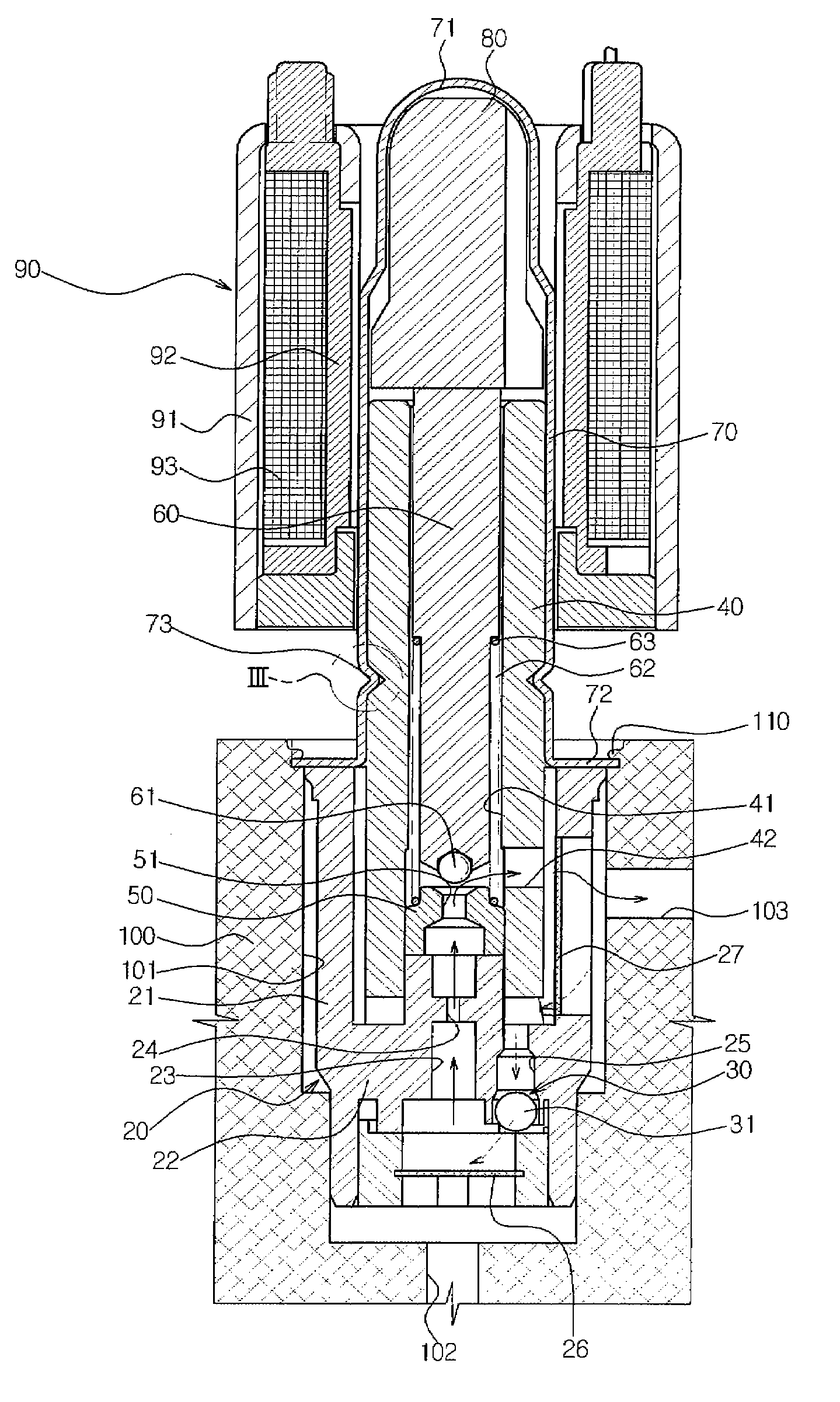
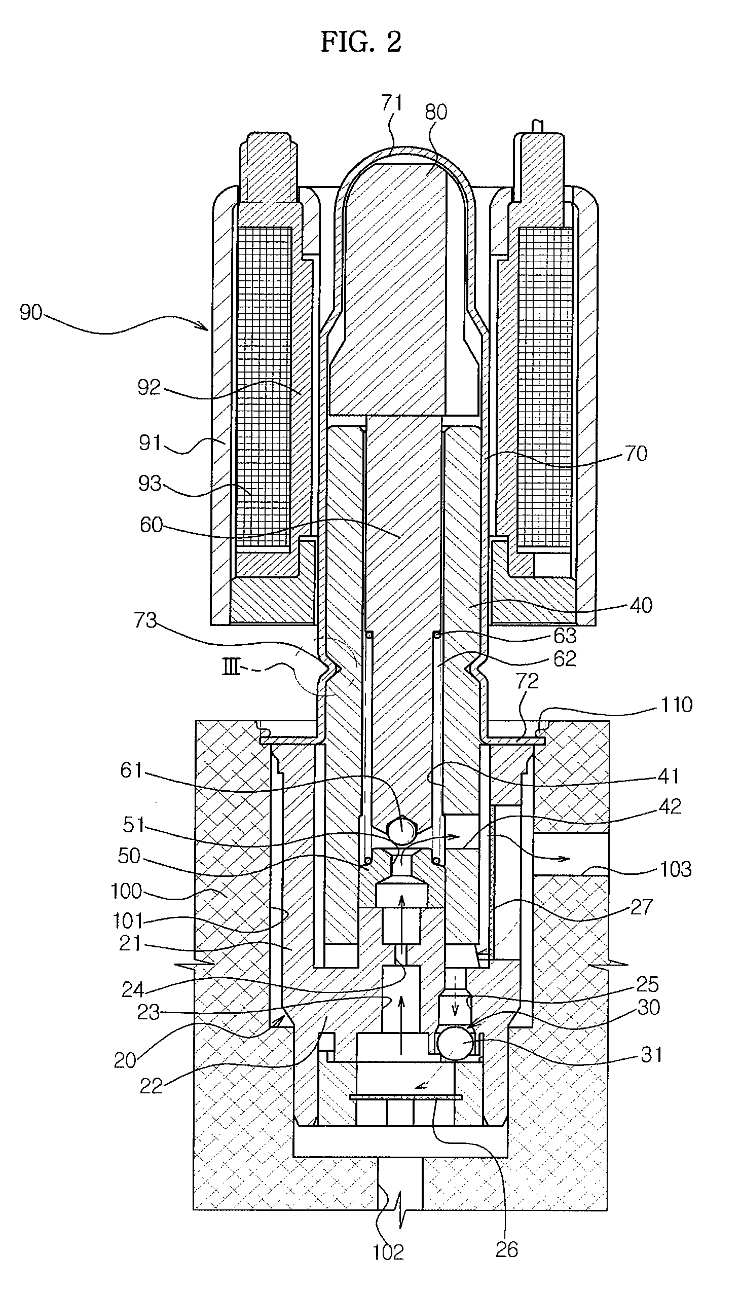
[0025]A solenoid valve for a brake system according to the present invention, as shown in FIG. 2, comprises a filter member 20 accommodated in a bore 101 of a modulator block 100, a valve core 40 coupled to the filter member 20, a valve seat 50 and a plunger 60 mounted in the valve core 40, a sleeve 70 coupled to an outer portion of the valve core 40, an armature 80 mounted in the sleeve 70, and an exciting coil assembly 90 mounted around the sleeve 70.

[0026]The valve core 40 is formed in a cylindrical shape, and has a through-hole 41 formed through the valve core 40 in a longitudinal direction and a fluid passage 42 formed in a radial direction so as to communicate ...


PUM


Abstract

A solenoid valve for a brake system, which has a simple constitution and can be easily manufactured with reduced manufacturing costs, is disclosed. A valve core is formed in a cylindrical shape, and has a through-hole formed in a longitudinal direction of the valve core and a fluid passage formed in a radial direction of the valve core so as to communicate with the through-hole. A sleeve is coupled to an outer surface of the valve core. The sleeve has a dome-shaped shielding portion at one end, and a flange portion to be fixed to a modulator block at the other end. An armature is slidably mounted in the sleeve. An exciting coil is provided to move the armature. A valve seat is fixed in the valve core, and has a first orifice. A plunger is mounted in the valve core. The plunger moves by movement of the armature to open or close the first orifice. A restoring spring is provided to press the plunger toward the armature. A filter member is coupled to the valve core to surround an outer surface and an end portion of the valve core, which are to be received in a bore of the modulator block. The filter member includes a filtering part to filter oil, a second orifice to rectify oil flow, and a check valve to permit oil to flow back when braking operation is released.

Description

CROSS-REFERENCE TO RELATED APPLICATION[0001]This application claims the benefit of Korean Patent Application No. 2007-0115643, filed on Nov. 13, 2007 in the Korean Intellectual Property Office, the disclosure of which is incorporated herein by reference.BACKGROUND OF THE INVENTION[0002]1. Field of the Invention[0003]The present invention relates to a solenoid valve for a brake system, and more particularly, to a solenoid valve for a brake system capable of being more easily manufactured and reducing manufacturing costs.[0004]2. Description of the Related Art[0005]Generally, an anti-lock brake system for vehicles serves to prevent locking of wheels by sensing slippage of the wheels and suitably controlling braking pressure applied to the wheels. The wheels of the vehicle do not slip during braking by means of the anti-lock brake system, whereby the steering performance of the vehicle is maintained, and the vehicle is stopped safely.[0006]In order to control braking pressure, the brak...

Claims


Application Information

Patent Timeline
Patent Type & Authority Applications(United States)
IPC IPC(8): B60T8/36F16K31/06B60T15/02
CPCF16K31/0665B60T8/363Y10T137/86976Y10T137/87507Y10T137/87555B60T8/36
Inventor LEE, SANG CHEOLLEE, CHUNG JAESEO, DONG IL
Owner HL MANDO CORP
Why Eureka
Try Eureka