Fixing device and image forming apparatus

a technology of fixing device and image forming apparatus, which is applied in the direction of electrographic process apparatus, instruments, optics, etc., can solve the problems of user forgetting to operate the lever, cumbersome manual release lever operation, and difficult jamming operation to release the sheet from the fixing nip

Active Publication Date: 2009-05-14
RICOH KK
View PDF6 Cites 85 Cited by
  • Summary
  • Abstract
  • Description
  • Claims
  • Application Information

AI Technical Summary

Benefits of technology

[0021]It is an object of the present invention to at lea...

Problems solved by technology

However, when there is jamming of the transfer sheet, if the apparatus stops with the recording sheet stuck in the fixing nip of the fixing device, the jam release operation to release the sheet from the fixing nip can be a tough task.
However, the manual release lever can be cumbersome to operate and there is a likelihood that the user may forget to operate the lever.
H5-173446 requires a dedicated motor to drive the cam, making the apparatus heavier as well as costlier.
Consequently, the amount of heat applied to the recording sheet by the fixing rollers tends to be inadequate.
As a result, the user must use more power for operating the conventional manual pressure releasing lever which makes the operation difficult.
In the configuration disclosed in Japanese Patent Application Laid-open No. 2001-318555, if stronger pressure is applied, the frictional force between the cam and the direct pressure exerting lever increases, decreasing the slidability and increasing the friction between the sliding contact surfaces.
In the mechanism disclosed in Japanese Patent Application Laid-open No. 2000-214718, if stronger pressure is applied, the frictional force between the release lever and the cover increases, decreasing the slidability and increasing the friction between the sliding contact surfaces.
However, the core end of the fixing member is rotatably supported by a shaft bearing.
In either case, the shaft bearing deforms and is damaged because of a localized force exerted on the outer periphery of the shaft bearing, r...

Method used


Image

  • Fixing device and image forming apparatus
  • Fixing device and image forming apparatus
  • Fixing device and image forming apparatus

Examples


Embodiment Construction

[0040]Exemplary embodiments of the present invention are explained below with reference to the accompanying drawings.

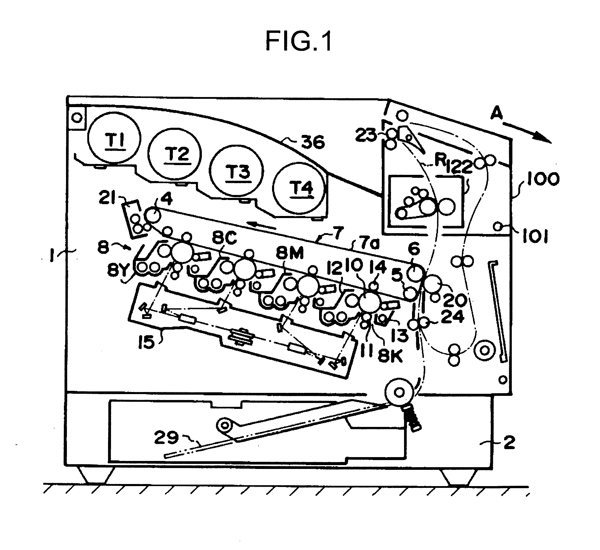
[0041]FIG. 1 is a schematic configuration diagram of an image forming apparatus according to an embodiment of the present invention. The image forming apparatus is a tandem type full color printer (hereinafter, “printer”) that uses the electrophotography method. The image forming apparatus can be a copying machine or a facsimile machine, apart from the printer.

[0042]The basic structure and operations of the printer are explained first with reference to FIG. 1 followed by the structure and function peculiar to the embodiment.

[0043]In the printer shown in FIG. 1, below an apparatus body 1, which forms the basic unit, is disposed a paper feeding unit 2 that contains transfer sheets 29 serving as a recording medium. An image forming unit 3 is disposed above the paper feeding unit 2. The image forming unit 3 includes an imaging block 8, an intermediate transfer unit 7, an ...


PUM


Abstract

A pressure releasing lever is operated to switch the position of a locking member between a pressure exertion position and a pressure release position. In the pressure exertion position a pressure exerting roller exerts pressure against another roller via a pressure exerting lever and in the pressure release position the pressure exerting roller separates from the roller. An elastic member pulls the locking member and a second end of the pressure exerting lever in a locking direction. A core end of the pressure exerting roller is rotatably supported by a shaft bearing. The pressure exerting lever engages with the shaft bearing.

Description

CROSS-REFERENCE TO RELATED APPLICATIONS[0001]The present application claims priority to and incorporates by reference the entire contents of Japanese priority document 2007-294232 filed in Japan on Nov. 13, 2007.BACKGROUND OF THE INVENTION[0002]1. Field of the Invention[0003]The present invention relates to a fixing device that fixes a toner image onto a recording sheet by head and pressure.[0004]2. Description of the Related Art[0005]In an image forming apparatus that uses the electrophotography method, electrostatic latent images are formed on the surface of a photosensitive drum functioning as an image carrying member, the electrostatic latent image is converted to a visible toner image by a developer, the toner image is transferred to a recording sheet by a transfer device, and borne to a fixing device, which fixes the toner image onto the recording sheet by applying heat and pressure. The recording sheet bearing the fixed image is then transported over a discharge path and disc...

Claims


Application Information

Patent Timeline
IPC IPC(8): G03G15/20
CPCG03G15/2032
Inventor YOSHINAGA, HIROSHISHINSHI, AKIRA
Owner RICOH KK
Why Eureka
Try Eureka