User-controlled water saving toilet

a technology of user-controlled water saving and toilets, applied in water installations, flushing devices, constructions, etc., can solve problems such as delay in closing, and achieve the effect of preventing unnecessary use of substantial quantities of water

a technology of user-controlled water saving and toilets, applied in water installations, flushing devices, constructions, etc., can solve problems such as delay in closing, and achieve the effect of preventing unnecessary use of substantial quantities of water

US20090126094A1Inactive Publication Date: 2009-05-21LAUBE STEPHEN G

Image

  • User-controlled water saving toilet
  • User-controlled water saving toilet
  • User-controlled water saving toilet

Examples


Embodiment Construction

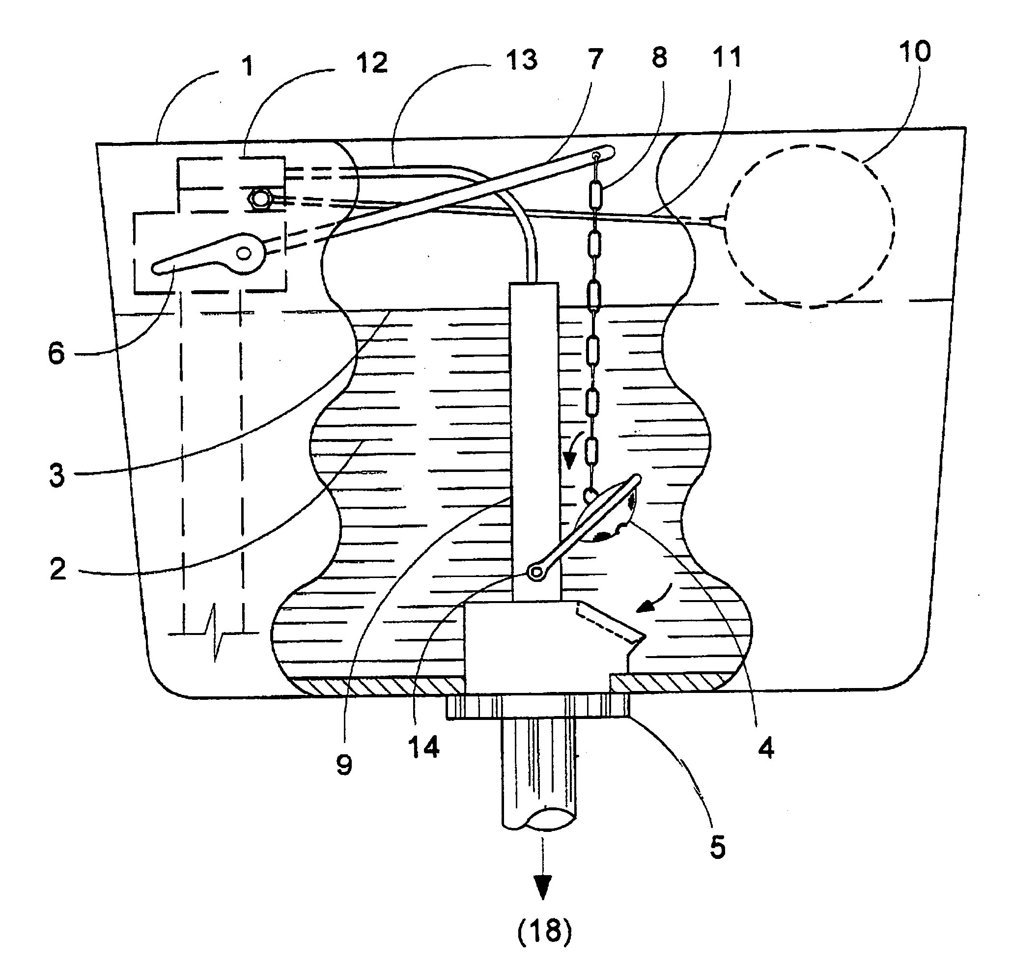
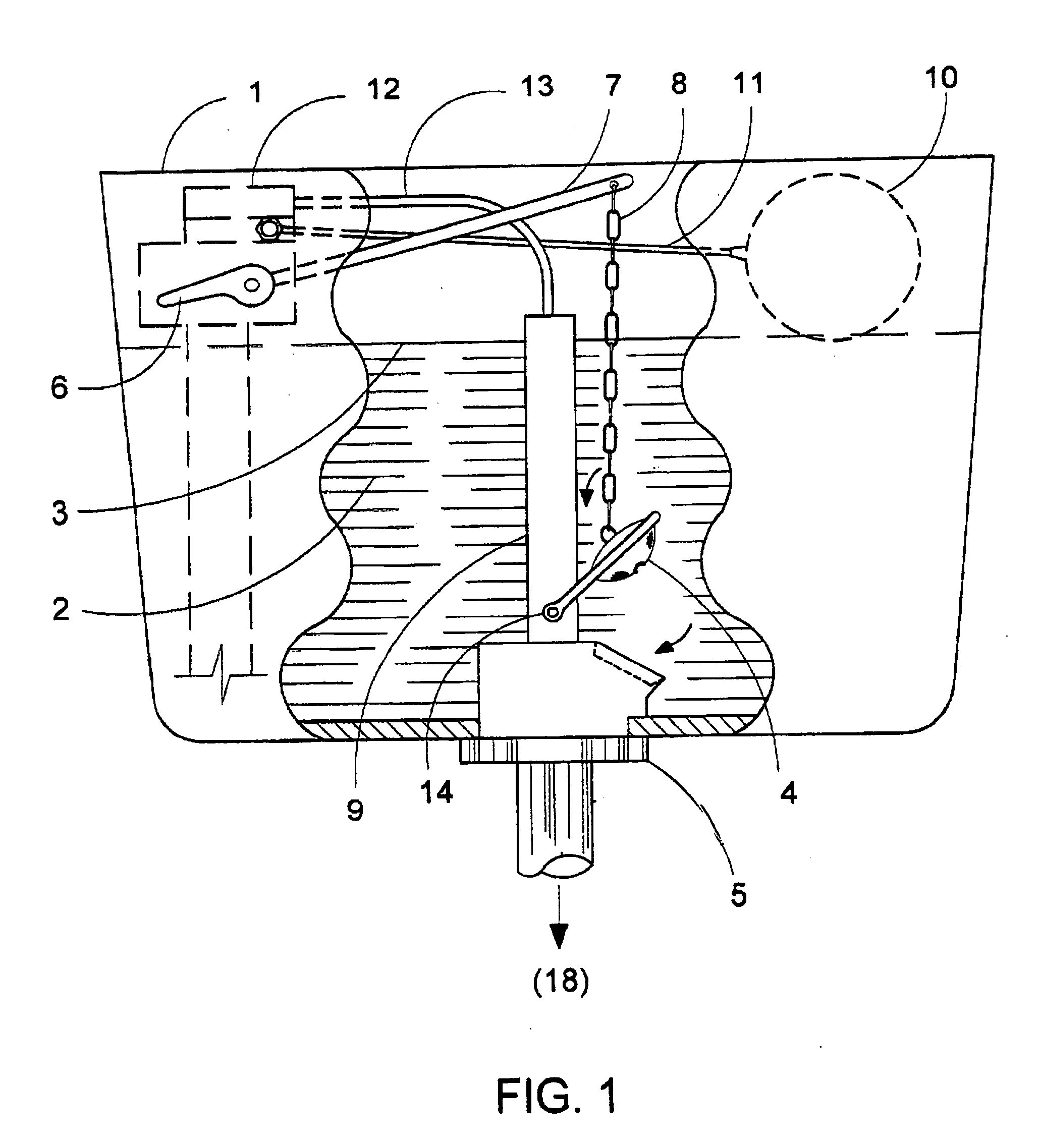
[0063]The discussion of the present inventive concept can best be initiated with a reference to FIG. 1 which presents a basic illustration of a typical flush toilet commonly used in the United States. The reservoir 1 contains an available volume of water 2 for flushing. The water 2 is prevented from exiting the reservoir 1 by the flapper valve 4 which is firmly maintained in its seated position atop the drain orifice 5 by hydrostatic pressure. Upon a user's downward push of the flush handle 6, the lever arm 7 rotates upward, imparting a vertical pull on the chain 8. The chain 8, being connected to the flapper valve 4, consequently lifts the flapper valve 4, which, being pivotally attached to the overflow tube 9, “pops up” from its seated position. The flapper valve 4, being buoyant, becomes suspended by flotation on the surface of the water 3 while the weight of the water 2 provides a head of pressure to initiate the flow of water 2 through the drain orifice 5.

[0064]During the flush...


PUM


Abstract

Methods and various devices for conserving water during the process of toilet flushing are disclosed. The method herein emphasizes retrofitting a toilet of the type typically having a reservoir, tank float, overflow tube, flush handle, lever arm, and a means of linkage to a flapper valve. Rigid internal components of the means of linkage are the primary improvements presented herein. The disclosed rigid devices replace the chain as the means of linkage in the toilet reservoir and thereby function, throughout the entire flush cycle, as a direct operator of the flapper valve, giving the user proactive control over the amount of water used in flushing. Devices, or kits, utilized in carrying out the water conserving method are disclosed which are easily installable into existing toilets of older design. The inventive concept empowers the user of a toilet to control the sufficiency of the total flush and consequently, the corresponding volume of water used, while operating the toilet with current flush controls.

Description

RELATED U.S. APPLICATION DATA[0001]This application claims the benefit of Provisional Application No. 60 / 989,003 filed Nov 19, 2007.CROSS-REFERENCES TO RELATED APPLICATIONSU.S. Patent Documents[0002]U.S. Pat. #DateClassificationInventor3,885,253May 27, 19754 / 67 Overbey, C.4,467,482Aug. 28, 19844 / 393Dyer, A.4,485,501Dec. 4, 19844 / 324Kloner, I.4,928,327May 29, 19904 / 395Kuhn, D.5,185,891Feb. 16, 19934 / 324Rise, L.5,289,594Mar. 01, 19944 / 415Wiewiorowski, T., et al5,341,522Aug. 30, 19944 / 415Munro, J.5,836,021Nov. 17, 19984 / 411Davidson,G., et al.5,996,135Dec. 07, 19994 / 324Hsleh, E.6,151,724Nov. 28, 20004 / 323Klingenstein, R.7,200,877Apr. 10, 20074 / 325Peng, K.U.S. Patent Application Publications[0003]Publication #Pub. DateCalssificationInventor2007 / 0101486May 10, 20074 / 392Torres, A.2007 / 0261158Nov 15, 20074 / 326Kimura, M, et al.Foreign Patent Documents[0004]Not applicable.STATEMENT OF FEDERALLY SPONSORED RESEARCH & DEVELOPMENT[0005]There is no federally sponsored research or development in co...

Claims


Application Information

Patent Timeline
21 May 2009
Publication
US20090126094A1
IPC
E03D1/14
CPC
E03D1/142; E03D2001/147; E03D5/092; Y02A20/40
Inventors
LAUBE, STEPHEN G.