Method for press-rolling a timepiece mainspring

a technology of timepiece mainspring and press-rolling machine, which is applied in the field of press-rolling the spiral part of the timepiece mainspring, can solve the problems of complex production of timepiece mainsprings, complex press-rolling operation, and requirement of perfect reproducibility, so as to avoid unnecessary processing installations and facilitate the handling of springs.

Active Publication Date: 2017-12-14
NIVAROX FAR
View PDF2 Cites 0 Cited by
  • Summary
  • Abstract
  • Description
  • Claims
  • Application Information

AI Technical Summary

Benefits of technology

[0009]The invention proposes to modify the press-rolling process to avoid a conventional, expensive operation of shaping the spring into a ring at the end of manufacture, for example to perform a treatment; and, more particularly, to produce an intermediate product that can be stored and handled flat.
[0010]The invention must make it possible to avoid the unnecessary use of processing installations with voluminous tools, and facilitate the handling of springs, while eliminating the usual operation of removal of the ring after the treatment.
[0011]The press-rolling process consists in forcing the strip spring between two rollers and a motorized shaft to create a three-point bending of the strip, making plastic deformation thereof possible.

Problems solved by technology

The manufacture of timepiece mainsprings is complex, and requires numerous steps, including a step of forming a ring and / or a step of press-rolling a portion of a wire, at one end of which an eye has previously been formed, to form the strip of the spring.
This press-rolling operation is complex, and requires perfect reproducibility.
The spring is awkward to handle following the press-rolling operation.

Method used


Image

  • Method for press-rolling a timepiece mainspring
  • Method for press-rolling a timepiece mainspring
  • Method for press-rolling a timepiece mainspring

Examples


Embodiment Construction

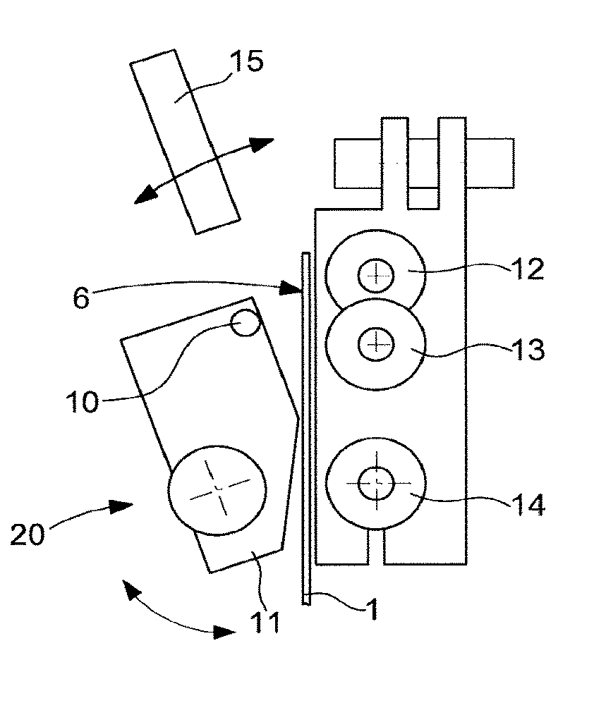
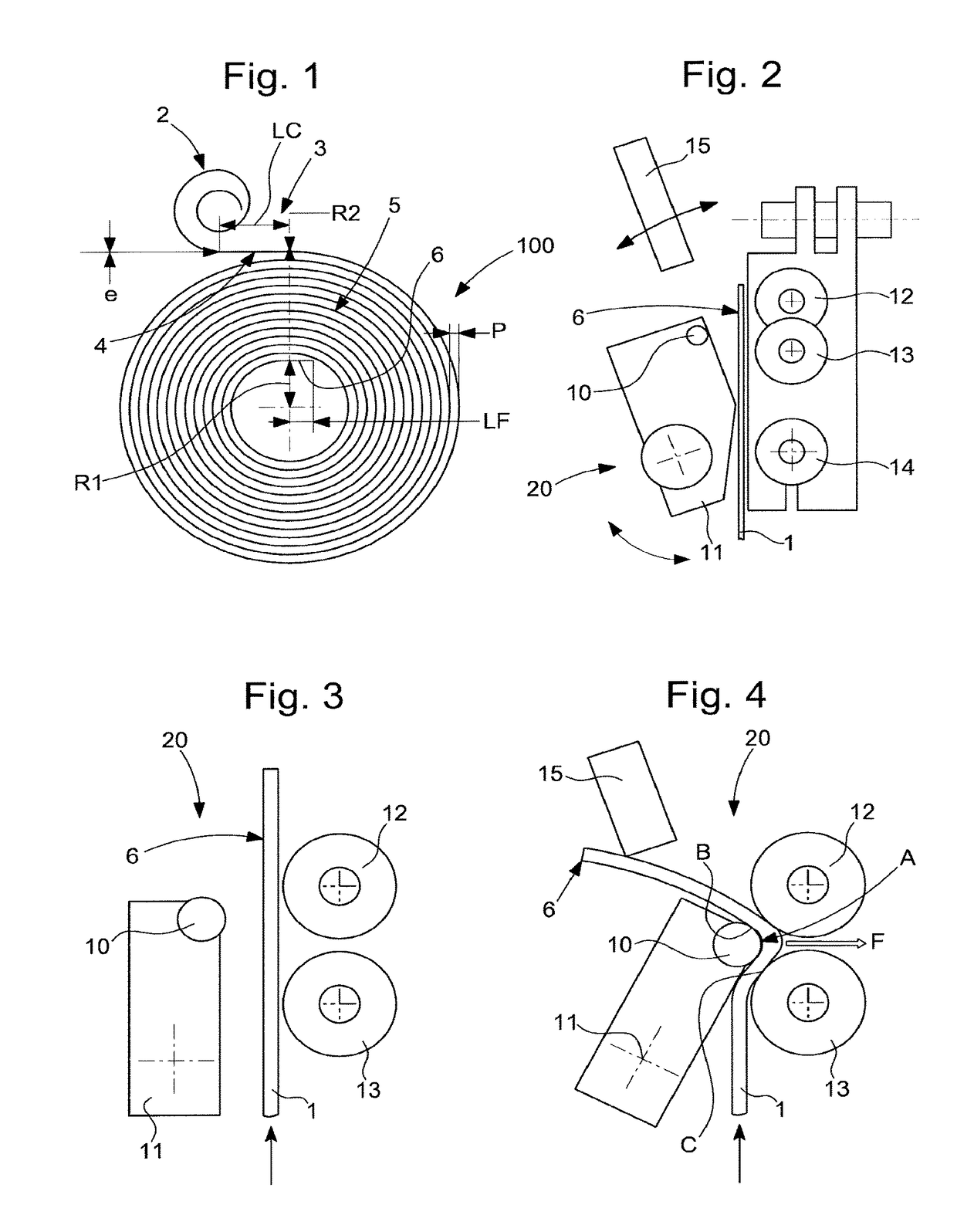
[0024]The invention concerns a method for press-rolling the spiral portion of a timepiece mainspring 100, from a pre-drawn and rolled wire 1.

[0025]This wire 1, of thickness “e”, includes in succession, from the start of the strip, an eye 2 formed prior to press-rolling, with a curvature whose centre is on an outer side of wire 1.

[0026]A first operation 1000 thus consists of the preparation of a drawn and rolled wire 1, with the completely formed eye 2. In particular, this eye includes, where appropriate, a usual opening arranged to cooperate with a hook of a barrel arbor. The preparation of this wire and eye is standard for those skilled in the art, specialized in the manufacture of mainsprings, and is not described in detail here.

[0027]This eye 2 is followed by a neck 3 of length LC, including an area of zero curvature 4 and forming an area of bending.

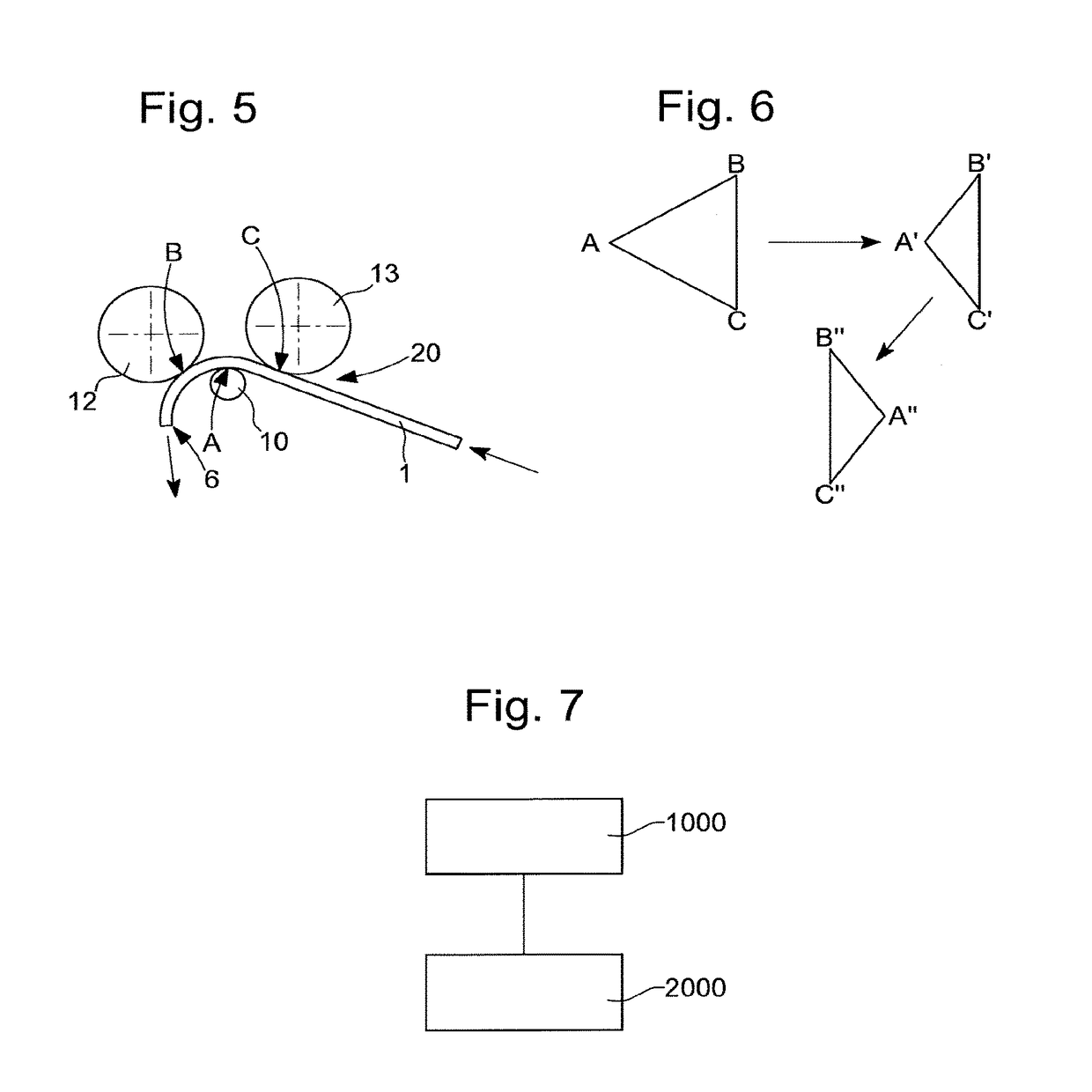
[0028]This neck 3 is followed by an accumulation area 5, which is the only area affected by the second operation 2000 according to t...


PUM

PropertyMeasurementUnit
degree of freedomaaaaaaaaaa
diameteraaaaaaaaaa
degree of freedomaaaaaaaaaa

Abstract

Method for press-rolling a mainspring, from a wire comprising a pre-formed eye, utilising a roller press comprising a first support and guide means exerting a force on the wire in a first contact area located between a second and a third contact area comprised in a second and a third support and guide means, in order to wind, beyond the eye, an accumulation area with an opposite curvature to that of the eye, and wherein, as the wire advances, the position of the first contact area is gradually moved away from the second and third contact areas, to vary the press-rolling radius from a first minimum value to a second maximum value at a neck junction between the accumulation area and the eye.

Description

[0001]This application claims priority from EP No. 16173898.4 filed on Jun. 10, 2016, the entire disclosure of which is hereby incorporated herein by reference.FIELD OF THE INVENTION[0002]The invention concerns a method for press-rolling the spiral part of a timepiece mainspring, from a wire that is pre-drawn and rolled, said wire comprising in succession, from the start of the strip, an eye formed prior to said press-rolling, with a curvature whose centre is on an outer side of said wire, said eye being followed by a neck comprising an area of zero curvature and forming an area of bending, and said neck being followed by an accumulation area which, during said press-rolling operation, is intended to be press-rolled into a spiral with a curvature whose centre is on an inner side of said wire, opposite to said outer side, said accumulation area ending with a strip end.[0003]The invention concerns the field of timepiece mainsprings and their manufacture.BACKGROUND OF THE INVENTION[000...

Claims


Application Information

Patent Timeline
Patent Type & Authority Applications(United States)
IPC IPC(8): B21F3/08G04D3/00G04B1/14G04B17/06B21D5/14B21F3/00
CPCB21F3/08G04B1/145B21D5/14G04D3/0041B21F3/00G04B17/066G04D3/0007B21F35/02Y10T29/49579G04B5/00
Inventor VANNOD, JONASCHARBON, CHRISTIAN
Owner NIVAROX FAR
Why Eureka
Try Eureka