Method for removing intra-microchannel bubbles and intra-microchannel dissolving and dispersing method

a technology of microchannel bubbles and dissolving methods, applied in the direction of instruments, separation processes, laboratory glassware, etc., can solve the problems of large air bubbles, inability to conduct accurate inspection, and large number of minute air bubbles, and achieve the effect of small siz

Inactive Publication Date: 2009-05-21
FUJIFILM CORP
View PDF3 Cites 23 Cited by
  • Summary
  • Abstract
  • Description
  • Claims
  • Application Information

AI Technical Summary

Benefits of technology

[0023]allowing the solution to flow in a second direction that is opposite to the first direction to move a gas-liquid interface of the solution, which is a rear end of the solution in the second direction, in a second direction at a second flow speed at which the bubbles adhered on the inner wall of the microchannel can maintain an adhesion position so as to collect the bubbles on the gas-liquid interface and make the bubbles disappear by exposing the bubbles to a gas.
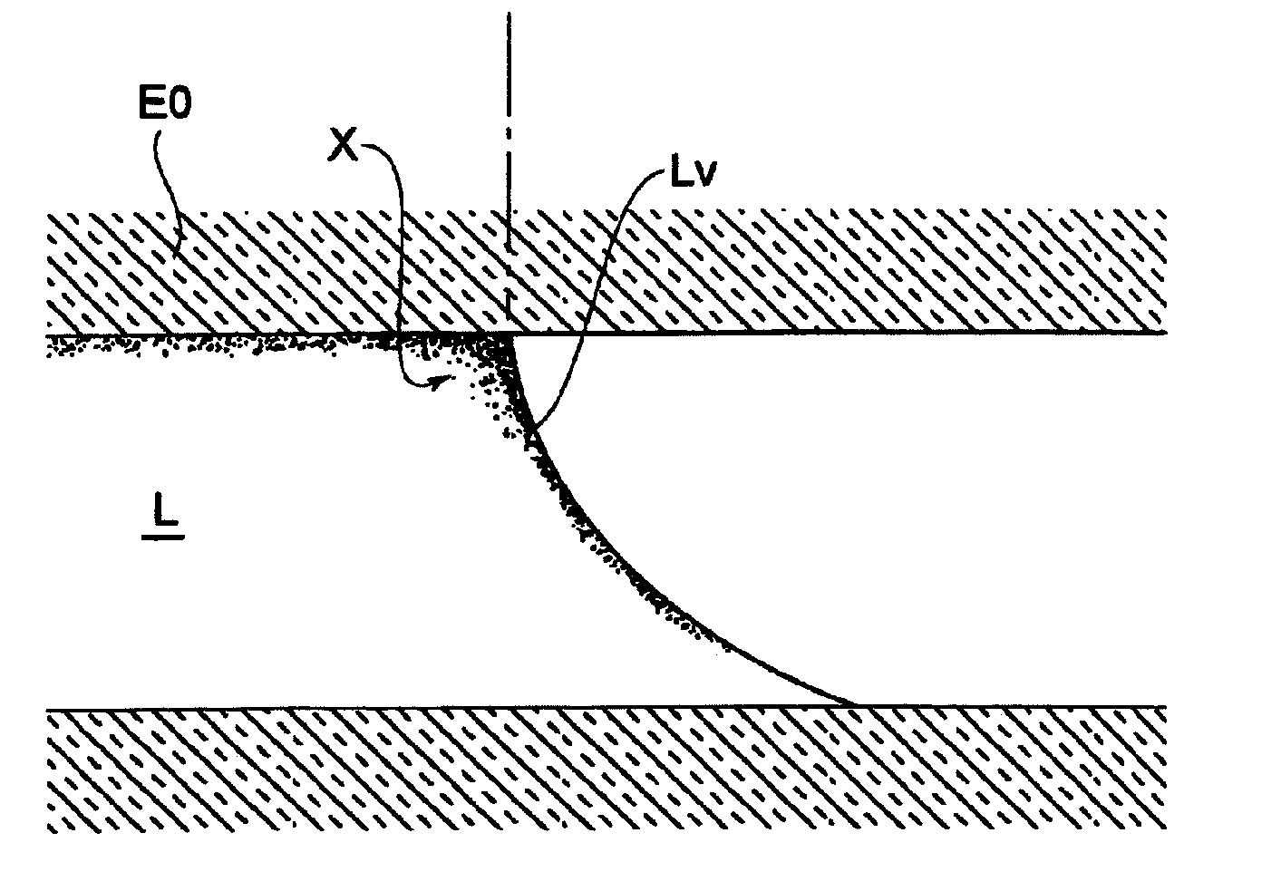
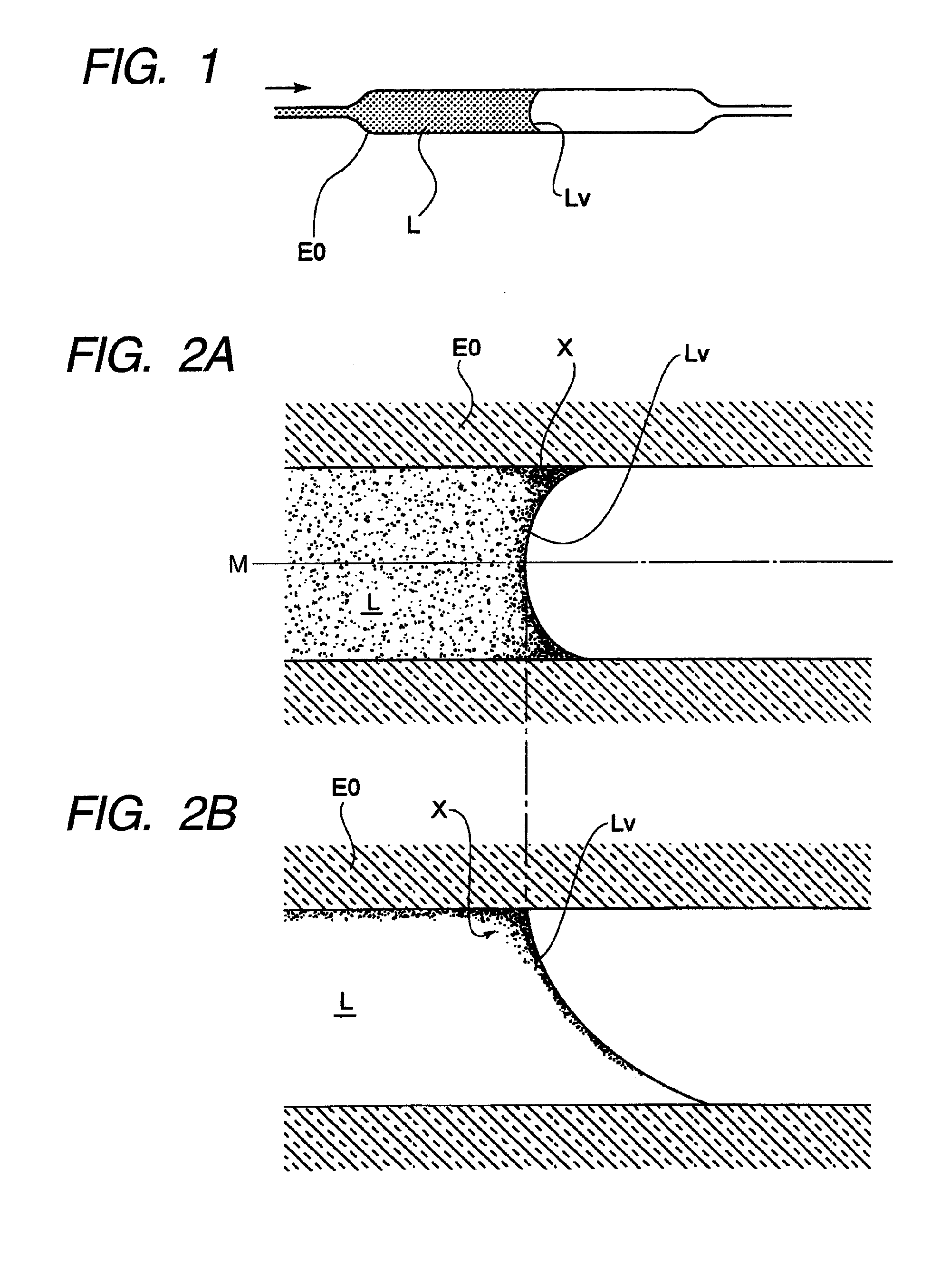
[0024]In doing this configuration, a solution is introduced into the microchannel at a flow speed higher than the penetrating speed with the capillary effect of the porous substance and the porous substances are dissolved, so that occurring air bubbles are suppressed to a small size. The flow speed of the solution is suppressed so that the bubbles in the solution are floated upward and are adhered on the inner wall of the channel. Next, the gas-liquid interface of the solution in the microchannel is moved at the flow speed at which the bubbles adhered on the inner wall of the channel can maintain the position, and the bubbles are collected on the gas-liquid interface at the rear end in the liquid traveling direction and are made to disappear.
[0025]Therefore, the bubbles occurring when a freeze-dried substance is dissolved can be suppressed without providing any special device. It is also made possible to deal with occurrence of unexpected air bubbles in the channel of the microchannel chip.

Problems solved by technology

However, since the freeze-dried reagent in the channel has a porous structure, if an inspected liquid, etc., is introduced and the freeze-dried reagent is dissolved therein, a large number of minute air bubbles occur and, for example, to optically inspect the reagent in the final step, the presence of the air bubbles becomes a large obstacle and an accurate inspection cannot be conducted; this is a problem.
However, if this method is applied to a freeze-dried substance carried in a channel of a microchannel chip, the apparatus becomes complicated; this is a problem.

Method used


Image

  • Method for removing intra-microchannel bubbles and intra-microchannel dissolving and dispersing method
  • Method for removing intra-microchannel bubbles and intra-microchannel dissolving and dispersing method
  • Method for removing intra-microchannel bubbles and intra-microchannel dissolving and dispersing method

Examples


Embodiment Construction

[0035]A preferred embodiment of a method for removing intra-microchannel bubbles according to an aspect of the invention will be discussed in detail with reference to the accompanying drawings.

[0036]FIG. 1 is a plan view to show a part of a channel of a microchannel chip according to the invention.

[0037]A mixing section E0 is a part of a microchannel; in FIG. 1, a liquid L introduced from the left contains a large number of minute air bubbles. When the liquid L is introduced into the mixing section E0, if air bubbles are recognized, the flow speed of the liquid L in the mixing section E0 is set to the speed at which at least the bubbles in the liquid float upward and are adhered on the inner wall of the mixing section E0 or less. As the state in which bubbles float upward, a state in which an internal swirling current does not occur is required and when such a state is entered, the bubbles contained in the liquid L float upward in the gravity direction without stagnation and are adh...


PUM

PropertyMeasurementUnit
flow speedaaaaaaaaaa
speedaaaaaaaaaa

Abstract

A method for removing intra-microchannel bubbles, which removes bubbles occurring in a microchannel, is provided; the method including: allowing a liquid that contains bubbles and is introduced into a microchannel to flow in a first direction at a first flow speed at which the bubbles float upward and can remain adhered on an inner wall of the microchannel or less; and then allowing the liquid to flow in a second direction that is opposite to the first direction to move a gas-liquid interface of the liquid, which is a rear end of the liquid in the second direction, in the second direction at a second flow speed at which the bubbles adhered on the inner wall of the microchannel can maintain an adhesion position so as to collect the bubbles on the gas-liquid interface and make the bubbles disappear by exposing the bubbles to a gas.

Description

BACKGROUND OF THE INVENTION[0001]1. Field of the Invention[0002]This invention relates to a method for removing intra-microchannel bubbles which removes bubbles occurring in a microchannel and an intra-microchannel dissolving and dispersing method which uses the method for removing bubbles to dissolve a porous substance.[0003]2. Description of the Related Art[0004]In recent years, a method using a microchannel chip as a system for realizing analysis and chemical reaction treatment of a trace amount of sample inexpensively and rapidly has been proposed.[0005]The microchannel chip is applied to an inspection apparatus for supplying a liquid to the microchannel chip and executing an inspection. As the inspection apparatus, for example, a biochemical treatment apparatus disclosed in Japanese Patent Laid-Open No. 2006-170654, etc., is available. It includes a stage for placing a biochemical reaction cartridge (microchannel chip) having chambers and a channel for allowing the chambers to ...

Claims


Application Information

Patent Timeline
Patent Type & Authority Applications(United States)
IPC IPC(8): B01D19/00
CPCB01D19/0005B01D19/0042B01L3/5023B01L3/502723B01L3/502784B01L2200/0673Y10T436/2575B01L2300/0816B01L2300/0864B01L2300/0867B01L2300/087B01L2400/0406B01L2400/0487B01L2200/0684
Inventor KARAKI, HIDEYUKITAKADA, GOROWAKABAYASHI, AKIRA
Owner FUJIFILM CORP
Why Eureka
Try Eureka