Electric power system for vehicle

a technology for electric power systems and vehicles, applied in electric/fluid circuits, electric devices, transportation and packaging, etc., can solve the problems of terminal voltage drop, difficult to obtain the effect of economic power consumption, and general fluctuation of residual generated electric power, etc., to reduce fuel consumption, simple structure, and small size

Active Publication Date: 2009-05-21
DENSO CORP
View PDF0 Cites 53 Cited by
  • Summary
  • Abstract
  • Description
  • Claims
  • Application Information

AI Technical Summary

Benefits of technology

[0021]This can realize the regeneration of a kinetic energy which is generated at each time of the vehicle speed reduction with a substantially maximum regenerative electric power generation function of the electric power system for a vehicle regardless of any operation fluctuation of the electrical loads and the main storage device. When compared with conventional techniques, the present invention provides the electric power system capable of decreasing the fuel consumption with a simple structure and a small size while preventing the regenerative electric power generation to decrease. Further, the present invention provides the electric power system capable of avoiding an excess voltage drop of the terminal voltage of the basic electric power system over an allowable voltage level, where such an excess voltage drop of the terminal voltage of the basic electric power system is caused when the electric power converter performs the transmission of the electric power of an excess amount in the forward electric power transmission.
[0022]In the electric power system according to the present invention, the control device controls the backward electric power transmission of the electric power converter so that the electric power generated by the alternator is not more than the specified value, preferably, equal to zero while the terminal voltage of the basic electric power system is maintained within the specified range. This control enables the sub storage device to rapidly charge the stored regenerative electric power, and as a result, the sub battery after completion of the rapid discharging can be charged with a future regenerative electric power generation.

Problems solved by technology

However, the magnitude of the residual generated electric power generally fluctuates according to various operational conditions of the alternator, the electric loads, and the main battery.
On the other hand, when a charging current for charging the sub battery is smaller than a current of the residual generated electric power, it becomes difficult to obtain the effect of economy in power consumption by generating the regenerative electric power during a vehicle speed reduction or braking.
A large voltage drop of the main battery causes a terminal voltage drop to be supplied to the electrical loads which are electrically connected to the main battery in addition to wasteful discharging of the main battery.
Thus, the voltage drop of the main battery will cause head lamps of a vehicle to decrease its intensity of illumination, and the speed of windshield wipers of the vehicle to be varied or drop.

Method used


Image

  • Electric power system for vehicle
  • Electric power system for vehicle
  • Electric power system for vehicle

Examples


embodiment

[0033]A description will be given of the electric power system for a vehicle according to an embodiment of the present invention with reference to FIG. 1 to FIG. 8.

(Circuit Structure)

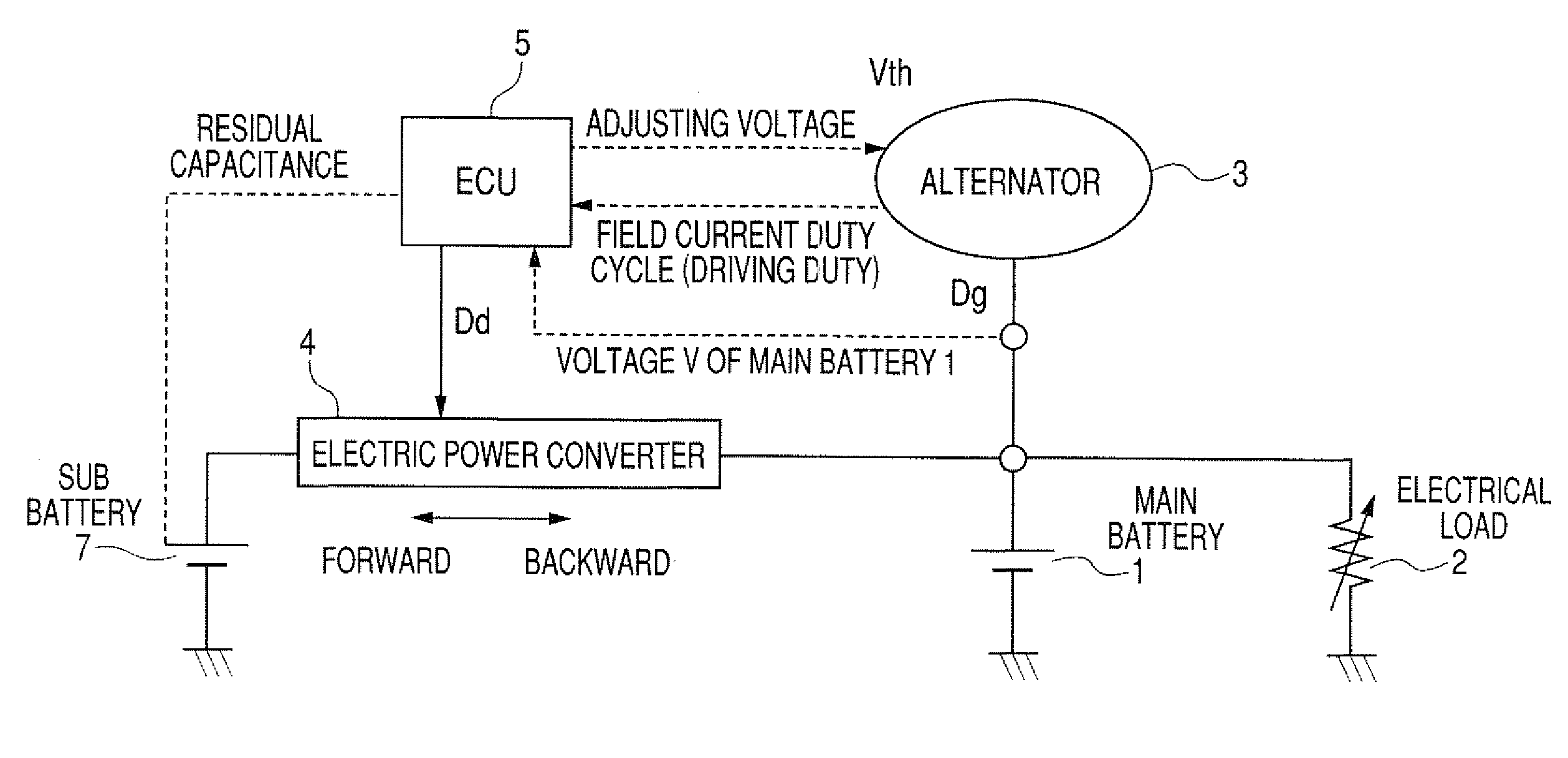
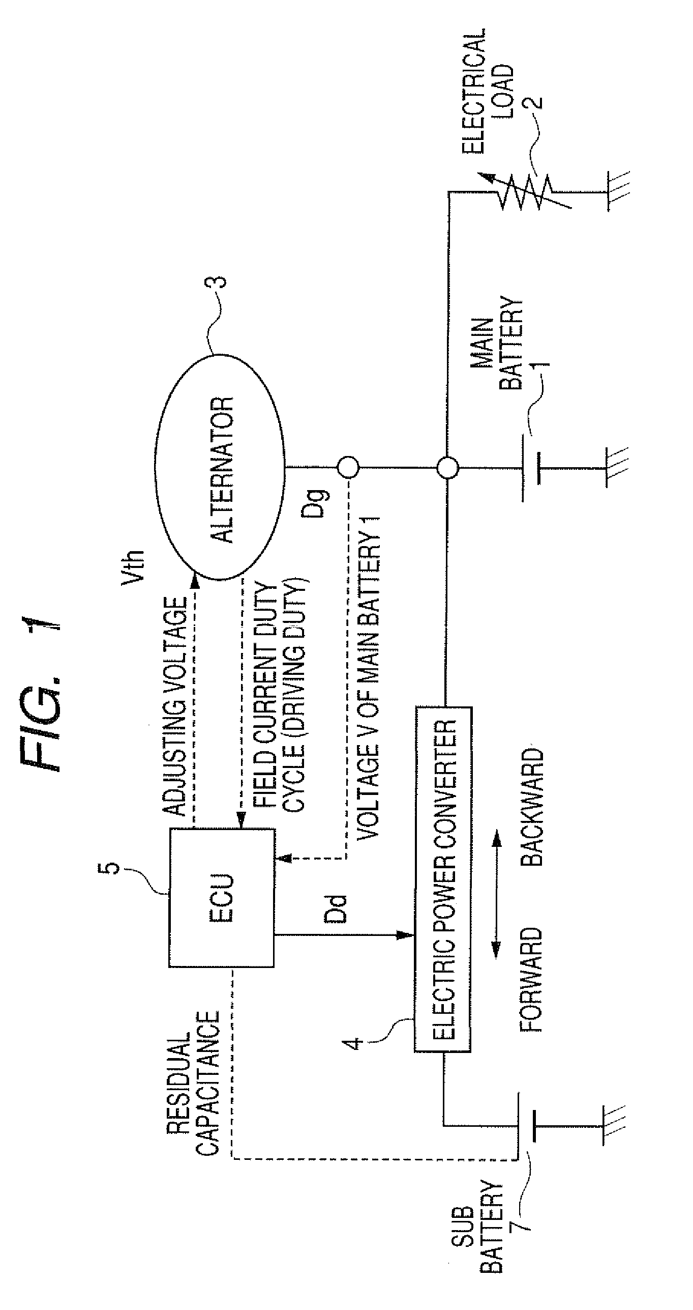
[0034]FIG. 1 is a block diagram showing a schematic circuit structure of the electric power system for a vehicle according to the embodiment of the present invention.

[0035]The electric power system according to the embodiment is comprised mainly of an on-vehicle alternator 3 (hereinafter, referred to as the “alternator 3” for short), a main battery 1 as a main electric power storage device (or a main storage device for short), a sub battery 7 as a sub electric power storage device (or a sub storage device for short), an electric control unit (ECU) 5 as a control device, and a DC-DC converter 4 as an electric power converter for a bi-directional electric power transmission. The main battery 1 and the sub battery 7 are rechargeable batteries.

[0036]The alternator 3 mounted on a vehicle is driven by a rotar...

first modification

(First Modification)

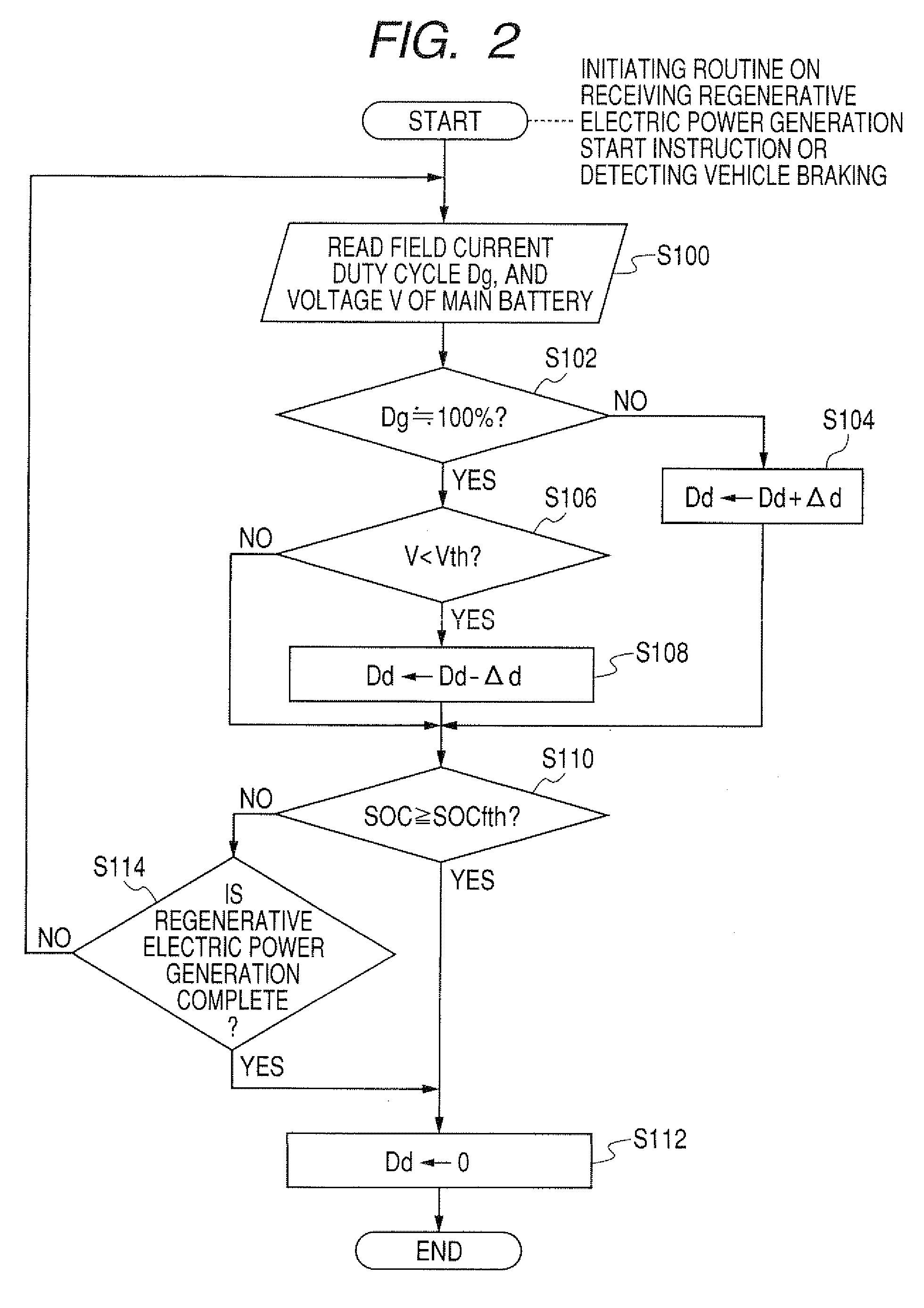
[0101]As described before in detail, the control device in the electric power system for a vehicle according to the embodiment of the present invention controls so that the sub battery 7 is charged during the regenerative electric power generation with the regenerative electric power which is equal to the residual generated electric power of the basic electric power system, and the battery 7 then rapidly discharges its stored electric power while maintaining the voltage V of the basic electric power system to the specified adjusting voltage Vth using a simple routine to control the PWM duty ratio Dd of the built-in switching element of the DC-DC converter 4 while directly or indirectly maintaining the voltage V of the basic electric power source to the specified adjusting voltage Vth.

[0102]There are various types of available control signals and functional values based on those control signals other than the adjusting voltage Vth and the voltage V of the basic po...


PUM


Abstract

An ECU in an electric power system for a vehicle controls a DC-DC converter so that an alternator transmits a residual generated electric power to a sub battery while a terminal voltage of a main battery is maintained within an optimally specified voltage range. This residual generated electric power is obtained by subtracting from a maximum generating electric power of the alternator an electric power to be consumed by electric loads and an electric power with which the main battery is charged. This can suppress any fluctuation of the voltage of electric power of the electric power system, namely, the output voltage of the alternator and the voltage of the main battery, and perform a maximum regenerative electric power generation. The sub battery is efficiently changed with the regenerative electric power.

Description

CROSS-REFERENCE TO RELATED APPLICATION[0001]This application is related to and claims priority from Japanese Patent Application No. 2007-300471 filed on Nov. 20, 2007, the contents of which are hereby incorporated by reference.BACKGROUND OF THE INVENTION[0002]1. Field of the Invention[0003]The present invention relates to an electric power system for a vehicle equipped with a plurality of electric power storage devices such as rechargeable batteries capable of supplying different terminal voltages to various types of electrical components as electrical loads mounted to a vehicle.[0004]2. Description of the Related Art[0005]There is known an electric power system for a vehicle. The electric power system is equipped with a plurality of electric power storage devices such as a main battery and a sub battery which are rechargeable. Each of the electric power storage devices outputs a different terminal voltage. Such an electric power system is comprised of an alternator, various electri...

Claims


Application Information

Patent Timeline
Patent Type & Authority Applications(United States)
IPC IPC(8): B60L1/00
CPCB60R16/03Y02T10/7005H02J7/1423H02J2310/46Y02T10/70
Inventor SENDA, TAKASHI
Owner DENSO CORP
Why Eureka
Try Eureka