Secondary trip system for circuit breaker

a circuit breaker and second trip technology, applied in circuit breaker switches, dynamo-electric relays, relays, etc., can solve the problems of long time period required to open the contact assembly, the time required for electrical activation of the actuation device and the movement of the mechanism,

a circuit breaker and second trip technology, applied in circuit breaker switches, dynamo-electric relays, relays, etc., can solve the problems of long time period required to open the contact assembly, the time required for electrical activation of the actuation device and the movement of the mechanism,

US20090128265A1Active Publication Date: 2009-05-21ABB SPA

Image

  • Secondary trip system for circuit breaker
  • Secondary trip system for circuit breaker
  • Secondary trip system for circuit breaker

Examples


Embodiment Construction

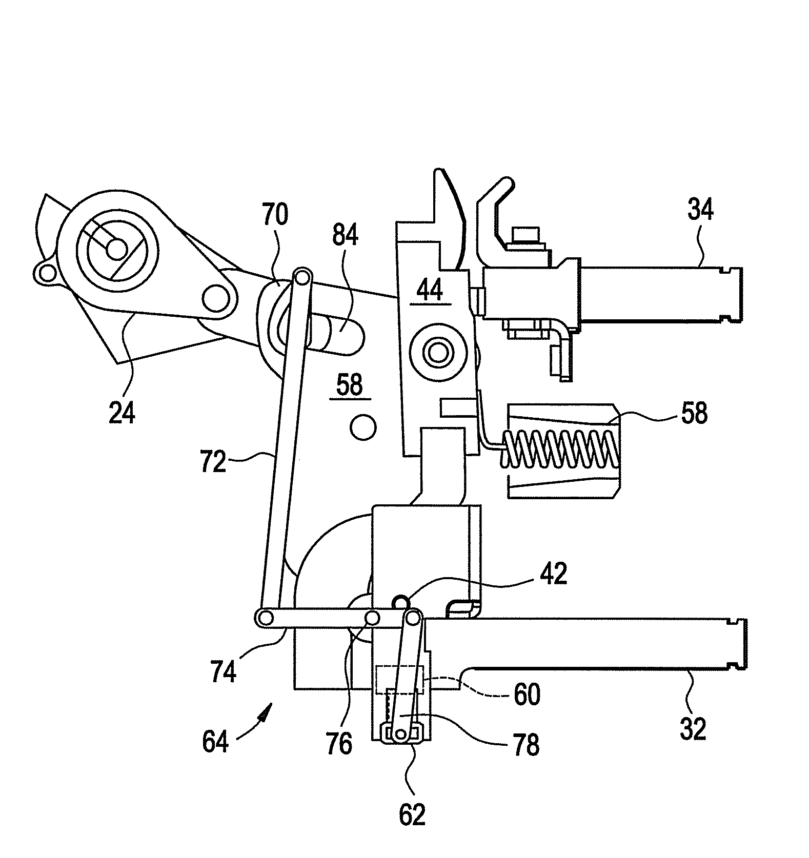
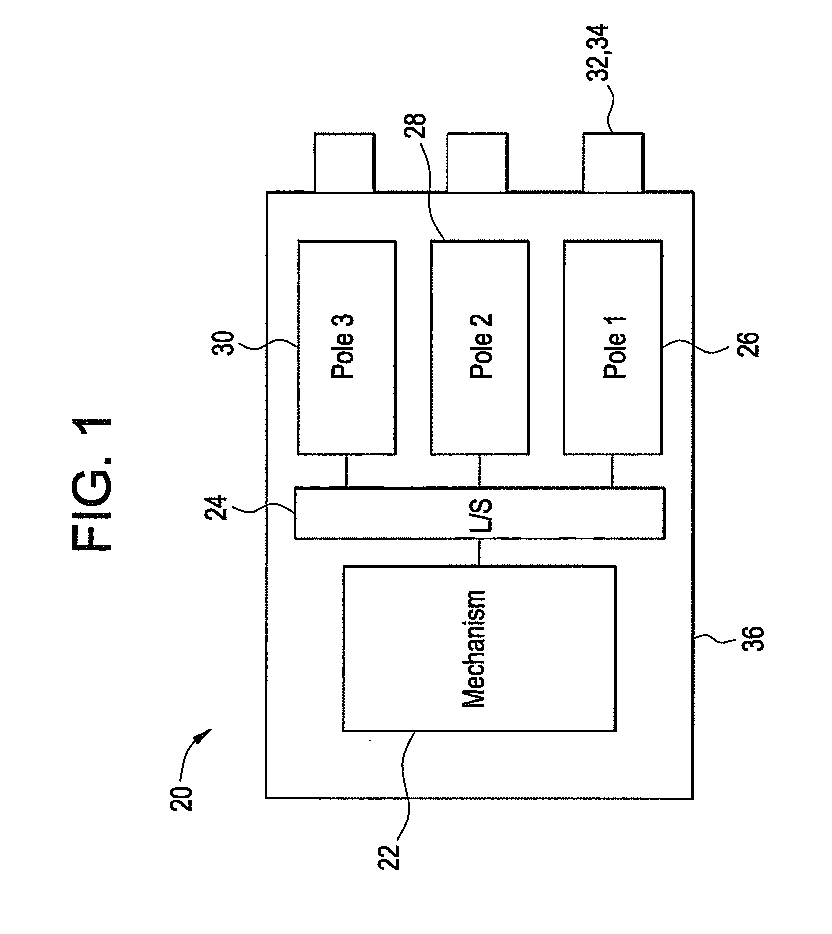
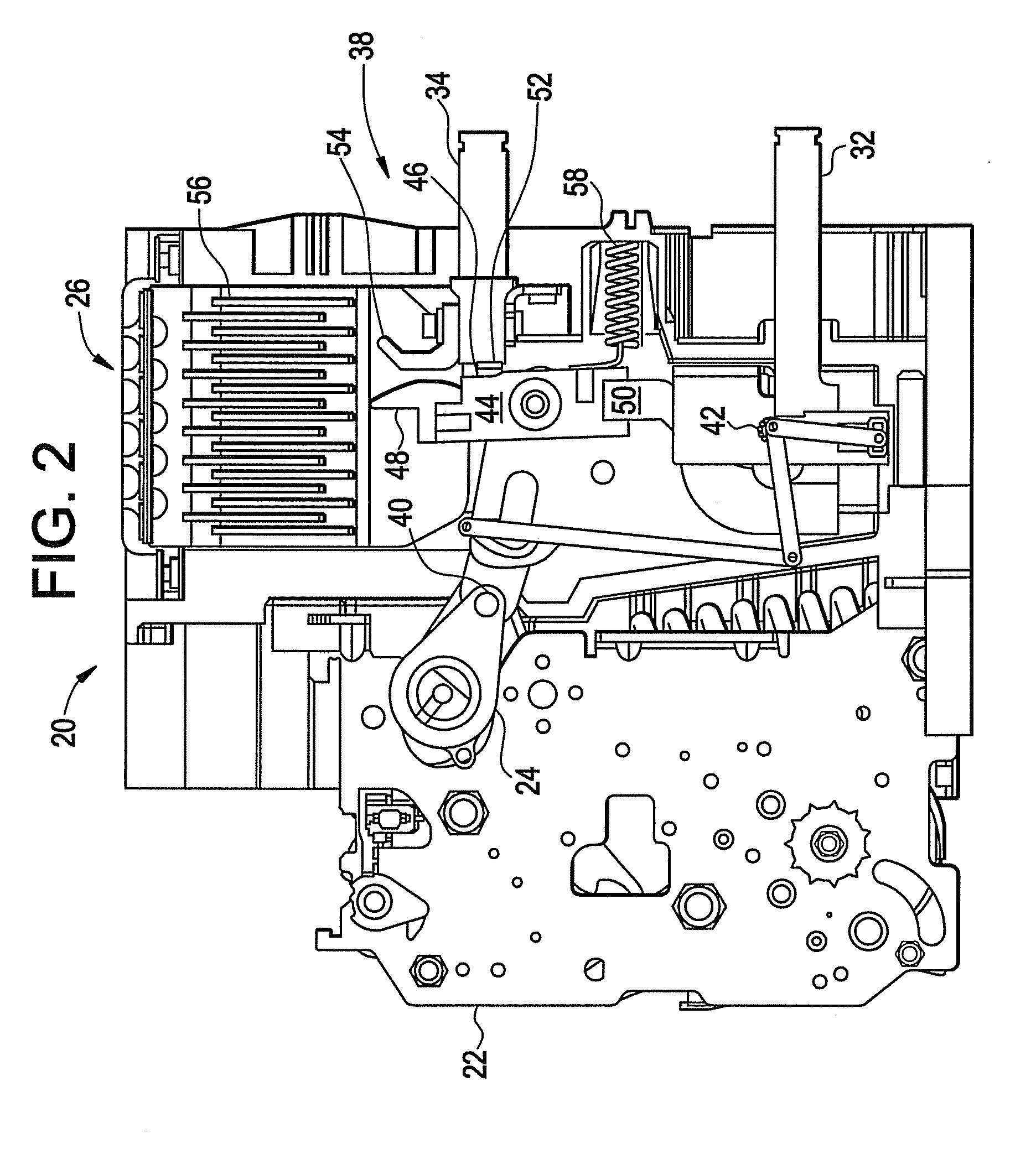
[0020]FIG. 1 illustrates a multi-pole circuit breaker 20 having a main mechanism 22. The mechanism 22 includes a lay shaft (ā€œL / Sā€) assembly 24 that couples the mechanism 22 to the pole assemblies 26, 28, 30. The mechanism provides a means for an operator to open, close and reset the pole assemblies 26, 28, 30 and will typically include an operator interface. The mechanism will further include a trip unit (not shown) that detects undesired electrical conditions and upon sensing of such a condition activates the mechanism 22. As will be described in more detail herein, the pole assemblies 26, 28, 30 conduct electrical current through the circuit breaker 20 and provide the means for connecting and disconnecting the protected circuit from the electrical power source.

[0021]In the exemplary embodiment, each pole of the multi-pole circuit breaker 20 carries a different electrical phase. Each of the pole assemblies 26, 28, 30 is coupled to a pair of conductors 32, 34 that connects the circu...


PUM


Abstract

A mechanism for a circuit breaker contact arm that allows current limiting by reducing the opening time is disclosed. A secondary trip assembly is arranged to actuate due to magnetic forces generated during an undesirable electrical condition such as a short circuit. The secondary trip system releases a contact arm assembly allowing the contact arm to rotate to an open position that interrupts the flow of electrical power.

Description

BACKGROUND OF THE INVENTION[0001]The subject matter disclosed herein relates to a mechanism for a circuit breaker. In particular, the subject matter disclosed herein relates to a mechanism coupled to a contact arm to provide current limiting functionality by reducing the opening time.[0002]Air circuit breakers are commonly used in electrical distribution systems. A typical air circuit breaker comprises an assembly of components for connecting an electrical power source to a consumer of electrical power called a load. The components are referred to as a main contact assembly. In this assembly, a main contact is typically either opened, interrupting a path for power to travel from the source to the load, or closed, providing a path for power to travel from the source to the load. In a particular type of circuit breaker, referred to as an air circuit breaker, the force necessary to open or close the main contact assembly is provided by an arrangement of compression springs. When the co...

Claims


Application Information

Patent Timeline
21 May 2009
Publication
US20090128265A1
IPC
H01H77/00
CPC
H01H71/2409; H01H2071/249; H01H2071/2427; H01H73/18; H01H73/02
Inventors
SUDHAKAR, SAPURAM; RAORANE, DEEPAK