Vehicle Deceleration Controller

a technology for deceleration controllers and vehicles, applied in vehicle position/course/altitude control, braking systems, instruments, etc., to achieve the effect of effectively recognizing warning braking and reliable carrying out of warning braking

Inactive Publication Date: 2009-05-21
TOYOTA JIDOSHA KK
View PDF24 Cites 23 Cited by
  • Summary
  • Abstract
  • Description
  • Claims
  • Application Information

AI Technical Summary

Benefits of technology

[0005]A major object of the present invention is to determine, on the basis of a deceleration state of a vehicle, whether or not warning braking is to be performed, to thereby reliably carry out the warning braking in a situation where the warning braking is needed and a crew of the vehicle can recognize the warning braking, and prevent the crew of the vehicle from feeling an unnatural sensation due to the warning braking in a situation where the warning braking is needed but the crew of the vehicle cannot effectively recognize the warning braking.

Problems solved by technology

On the other hand, when the vehicle is being decelerated by the travel control means, the deceleration of the vehicle is equal to or greater than the reference value, and it is difficult for the crew of the vehicle to effectively recognize the warning braking, it is possible to reliably prevent the crew of the vehicle from feeling an unnatural sensation due to the warning braking.
On the other hand, when the vehicle is being decelerated by the travel control means, the target deceleration of the warning braking means is equal to or less than the sum of the deceleration of the vehicle and the predetermined value, and it is difficult for the crew of the vehicle to effectively recognize the warning braking, it is possible to reliably prevent the crew of the vehicle from feeling an unnatural sensation due to the warning braking.

Method used


Image

  • Vehicle Deceleration Controller
  • Vehicle Deceleration Controller
  • Vehicle Deceleration Controller

Examples


first embodiment

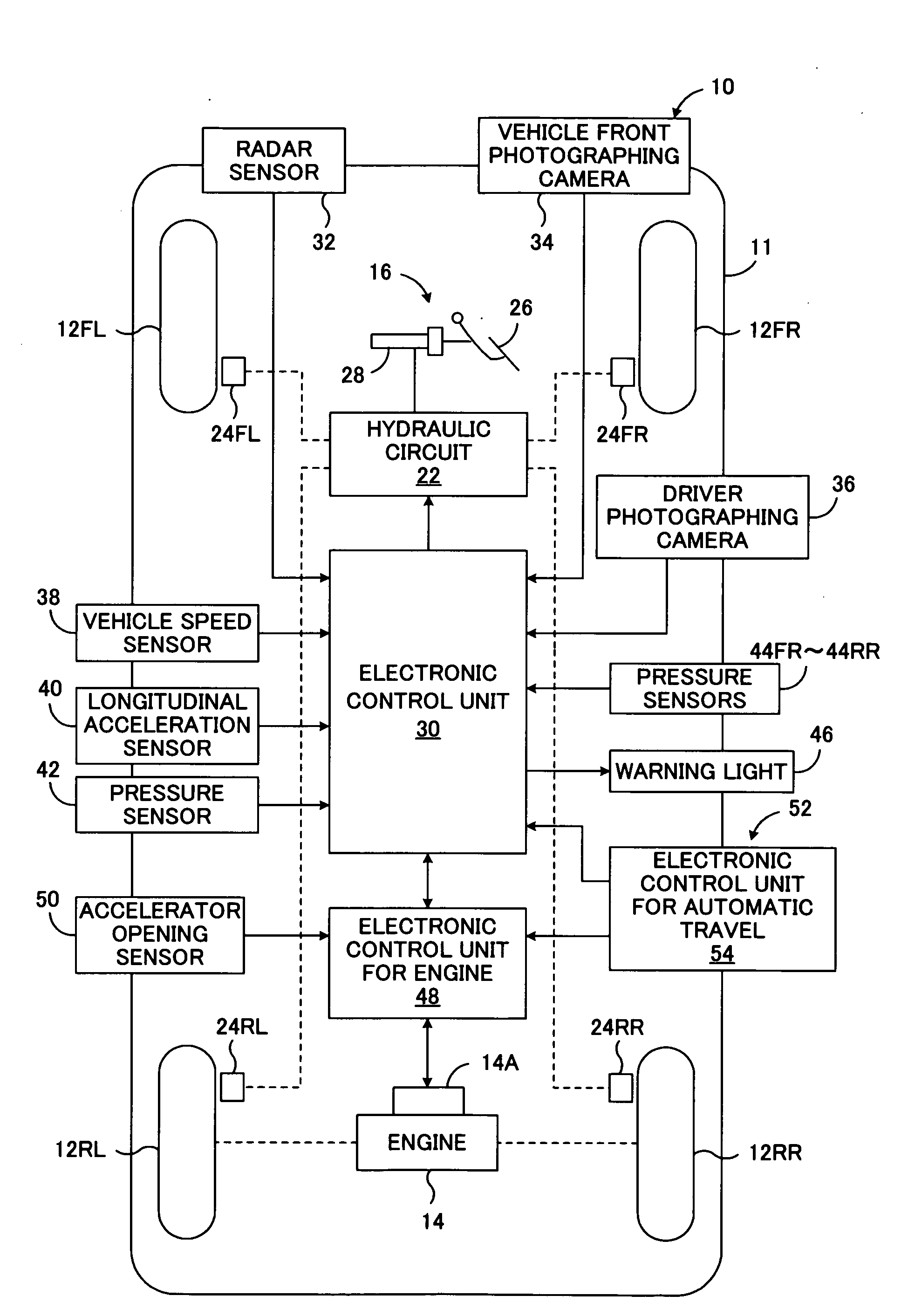
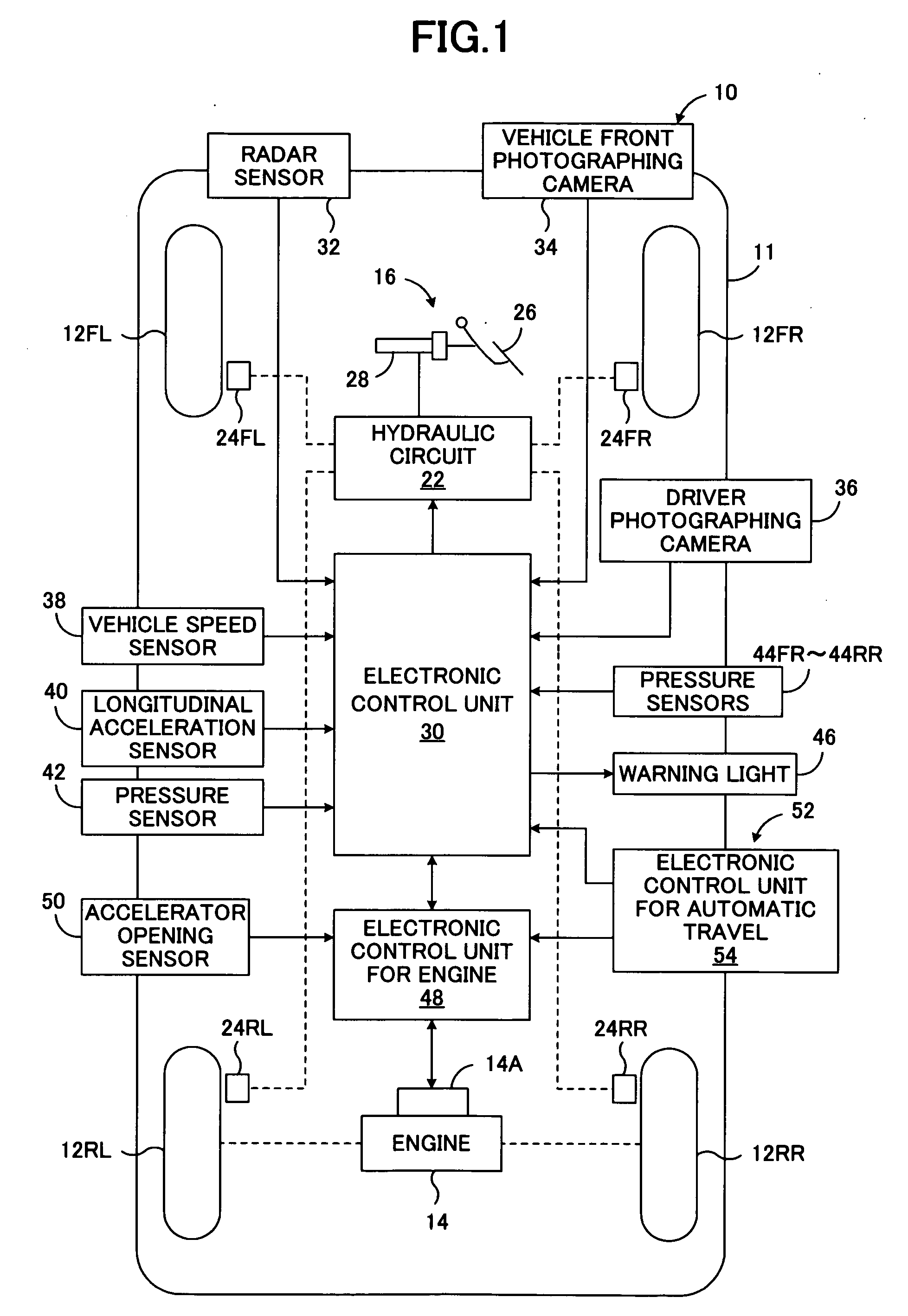
[0064]FIG. 1 is a schematic diagram showing a first embodiment of a braking and driving force controller of a vehicle according to the present invention, the controller being applied to a four-wheel drive vehicle of an in-wheel motor type.

[0065]FIG. 1 is a schematic diagram showing one embodiment of a deceleration controller according to the present invention.

[0066]A deceleration controller 10 is mounted on a vehicle 11. The vehicle 11 is a four-wheel automobile, including a right front wheel 12FR, a left front wheel 12FL, a right rear wheel 12RR, and a left rear wheel 12RL. The vehicle 11 also includes an engine 14 that serves as drive source and a braking apparatus 16 that generates braking force. The engine 14 includes a throttle valve actuator 14A for driving a throttle valve thereof. The braking apparatus 16 includes a hydraulic circuit 22, a wheel cylinder 24FR for the right front wheel, a wheel cylinder 24FL for the left front wheel, a wheel cylinder 24RR for the right rear w...


PUM


Abstract

An object of the present invention is to reliably carry out warning braking in a situation where the warning braking is needed and a crew can recognize the warning braking, and prevent the crew from feeling an unnatural sensation due to the warning braking in a situation where the warning braking is needed but the crew cannot effectively recognize the warning braking. If an obstacle is present ahead of the vehicle, the driver does not carry out brake operation, the driver is looking aside, and the vehicle may collide with the obstacle, the maximum target deceleration Gbt2max for the warning braking is computed. If automatic travel control is not carried out or if automatic travel control is being carried out and its target deceleration Gbt4 is less than a reference value Gbt4s smaller than the maximum target deceleration Gbt2max, the warning braking is carried out. However, when the target deceleration Gbt4 for the automatic travel control is larger than the allowable reference value Gbt4s for warning braking, the warning braking is not carried out.

Description

TECHNICAL FIELD[0001]The present invention relates to a deceleration controller for a vehicle, and more particularly, to a deceleration controller for a vehicle which performs warning braking for issuing a warning to a crew of the vehicle.BACKGROUND ART[0002]As described in, for example, Japanese Patent Application Laid-Open (kokai) No. 2005-31967, a known deceleration controller for a vehicle, such as an automobile, performs, as a warning to a driver, warning braking for decelerating the vehicle by means of braking when deceleration is needed from the viewpoint of a risk of colliding with a front obstacle and securing of safety. According such a deceleration controller, in a situation where deceleration is needed from the viewpoint of a risk of colliding with a front obstacle and securing of safety, a warning which indicates the necessity of deceleration can be issued to a driver by means of deceleration of the vehicle.[0003]In general, the warning braking is performed in a situati...

Claims


Application Information

Patent Timeline
Patent Type & Authority Applications(United States)
IPC IPC(8): B60Q1/50B60T7/12B60W30/00B60W30/09B60W50/14B60W50/16
CPCB60T7/22B60T2201/02B60W2420/52B60W50/14B60W30/02
Inventor NAGATA, SHINICHIOKITA, TOSHINORI
Owner TOYOTA JIDOSHA KK
Why Eureka
Try Eureka