Method for Manufacturing a Heat Exchanger Containing a Phase-Change Material, Exchanger Obtained and Uses at High Temperatures

a technology of phase-change material and heat exchanger, which is applied in the direction of stationary tubular conduit, stationary plate conduit, stationary tubular conduit, etc., can solve the problems of limited application field, low mechanical strength of the exchanger, and limited use of molten salts, etc., to achieve simple implementation, reduce cost, and great compactness

Inactive Publication Date: 2015-09-24
COMMISSARIAT A LENERGIE ATOMIQUE ET AUX ENERGIES ALTERNATIVES
View PDF11 Cites 19 Cited by
  • Summary
  • Abstract
  • Description
  • Claims
  • Application Information

AI Technical Summary

Benefits of technology

[0074]The manufacturing process according to the invention is clearly distinguished from the processes for manufacturing heat exchangers incorporating a PCM material according to the prior art, in particular from patent DE102010004358, in that it makes it possible to shape the PCM cells according to any geometry in order to promote reactant mixing and heat exchanges and any dimension on the millimeter or centimeter scale, while being simple to implement and having a lower cost.
[0075]The inventors thought of applying the already proven technique for manufacturing plate exchangers which consists of an assembly by diffusion welding or by brazing in order to produce cells for containing a PCM material. Surprisingly, although simple to implement, no one had thought to do it until now. Indeed, assembly by

Problems solved by technology

It is furthermore suggested in this publication that the large increase in volume during melting, typically 1% to 30%, the supercooling and the cost are limitations to the use of molten salts.
The manufacturing technique described in this U.S. Pat. No. 4,124,018 requires thin wall thicknesses, which results in a low mechanical strength of the exchanger and therefore limits the field of application thereof.
The use of such an exchanger cannot thus be envisaged at high pressures and/or high temperatures.
Patent DE102010004358 discloses a ceramic honeycomb exchanger structure obtained by an extrusion technique, which enables the storage of PCM (salt or metal) having a high melting point, ty

Method used


Image

  • Method for Manufacturing a Heat Exchanger Containing a Phase-Change Material, Exchanger Obtained and Uses at High Temperatures
  • Method for Manufacturing a Heat Exchanger Containing a Phase-Change Material, Exchanger Obtained and Uses at High Temperatures
  • Method for Manufacturing a Heat Exchanger Containing a Phase-Change Material, Exchanger Obtained and Uses at High Temperatures

Examples


Embodiment Construction

[0096]Other advantages and features of the invention will emerge more clearly on reading the detailed description of exemplary embodiments of the invention given by way of illustration and non-limitingly with reference to the following figures, among which:

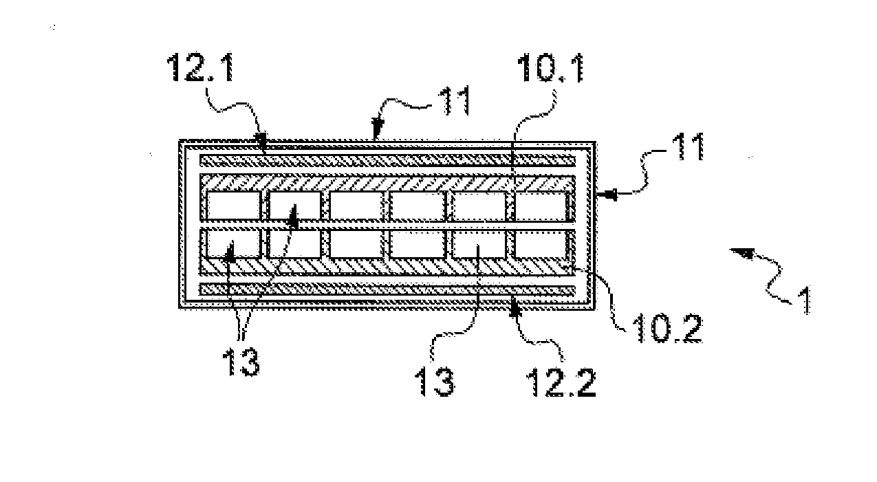
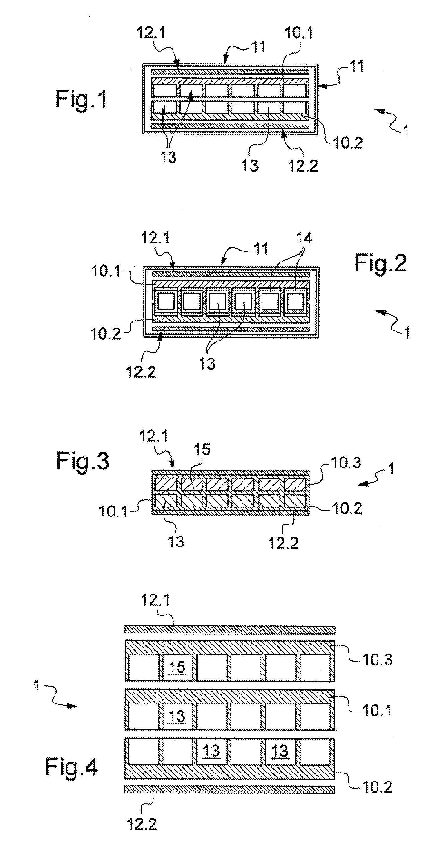
[0097]FIG. 1 is an exploded schematic view of various components of a heat exchanger and of the leaktight container used during a HIP pressing manufacturing process according to the prior art;

[0098]FIG. 2 is an exploded schematic view of various components of a heat exchanger and of the leaktight container used during a HIP pressing manufacturing process according to a variant of FIG. 1;

[0099]FIG. 3 is a schematic transverse cross-sectional view of a heat exchanger module incorporating a phase-change material PCM according to the invention;

[0100]FIG. 4 is an exploded schematic view of various components of an exchanger module according to FIG. 3;

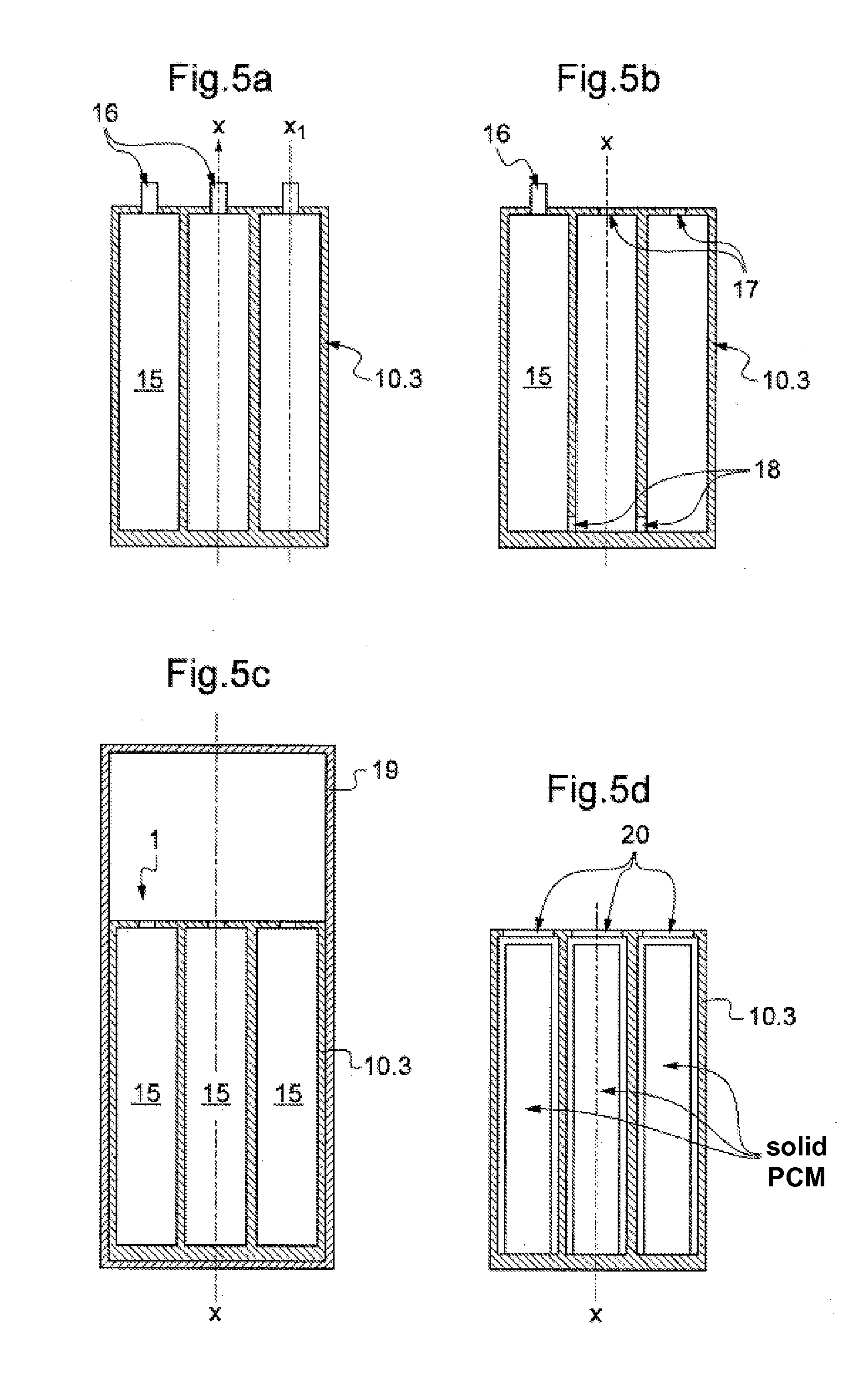
[0101]FIGS. 5A to 5D illustrate, in a longitudinal cross-sectional view, various steps...


PUM

PropertyMeasurementUnit
Heightaaaaaaaaaa
Heightaaaaaaaaaa
Temperatureaaaaaaaaaa

Abstract

The invention relates to a heat-exchanger module (1) comprising at least one fluid circuit comprising at least one fluid-circulation channel (13), at least one cell containing a phase-change material (PCM) such as a metal alloy or salt, at least the cell(s) being defined by walls (10) of at least one first metal plate (10.1, 10.2, 10.3) which can be welded, diffusion welded or brazed onto a second metal plate (10.1, 10.2, 10.3). The invention relates to the related manufacturing methods as well as to the uses at high temperatures.

Description

TECHNICAL FIELD[0001]The present invention relates to a process for producing a heat exchanger module comprising at least one fluid circuit comprising at least one fluid circulation channel, at least one cell containing a phase-change material (PCM). A heat exchanger module according to the invention may comprise at least one outer face intended to be in contact with a heat flux originating from a surrounding medium.[0002]An exchanger obtained according to the process of the invention makes it possible, owing to the phase-change material that it incorporates, to store heat or to smooth out temperature fluctuations of systems.[0003]The applications targeted by an exchanger according to the invention are numerous and relate to the processes in which the heat exchanges are carried out at high temperatures. For the purposes of the invention, the expression “high temperatures” is understood to mean temperatures above 200° C., preferably between 400 and 800° C.[0004]More particularly, for...

Claims


Application Information

Patent Timeline
IPC IPC(8): B23P15/26F28D20/02
CPCF28D20/02B23P15/26F28F2275/061F28D1/0308F28D7/106F28D9/0031F28D20/003F28D20/021F28D2020/0008Y10T29/4935Y02E60/14
Inventor BENGAOUER, ALAINROUX, GUILHEM
Owner COMMISSARIAT A LENERGIE ATOMIQUE ET AUX ENERGIES ALTERNATIVES
Why Eureka
Try Eureka