Method of manufacturing color filter, color filter, image display device and electronic apparatus

Inactive Publication Date: 2009-05-21
SEIKO EPSON CORP
View PDF2 Cites 5 Cited by
  • Summary
  • Abstract
  • Description
  • Claims
  • Application Information

AI Technical Summary

Benefits of technology

[0016]Accordingly, it is an object of the present invention to provide a method of manufacturing a color filter that can suppress generation of uneven color, uneven color density and color heterogeneity.

Problems solved by technology

This results in an increased cost for manufacturing the color filter.
Further, such a method is not preferable in view of resource saving.
However, in the method of manufacturing the color filter disclosed in the JP-A 2002-372613, there is a problem in that it is very difficult to equalize amounts of droplets ejected from respective nozzles of a droplet ejection head into cells formed on a substrate and make them always constant because of many factors of errors.
However, if the total amount of ink supplied to each of the respective cells differs from to each other, uneven color concentration generates at various portions of the coloring parts of the same color.
As a result, uneven color and uneven color density as well as color heterogeneity (irregular lightness variation) which is comprised of many strips of such uneven color or uneven color density also generate at various portions in a manufactured color filter corresponding to such coloring parts of the color filter.
Therefore, reliability of the manufactured color filter lowers.

Method used


Image

  • Method of manufacturing color filter, color filter, image display device and electronic apparatus
  • Method of manufacturing color filter, color filter, image display device and electronic apparatus
  • Method of manufacturing color filter, color filter, image display device and electronic apparatus

Examples


first embodiment

[0074]Ink for Use in Color Filter

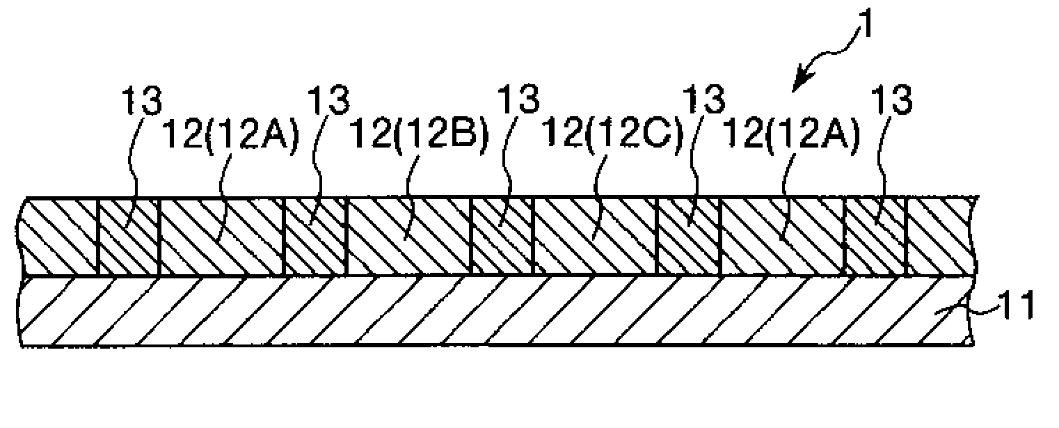
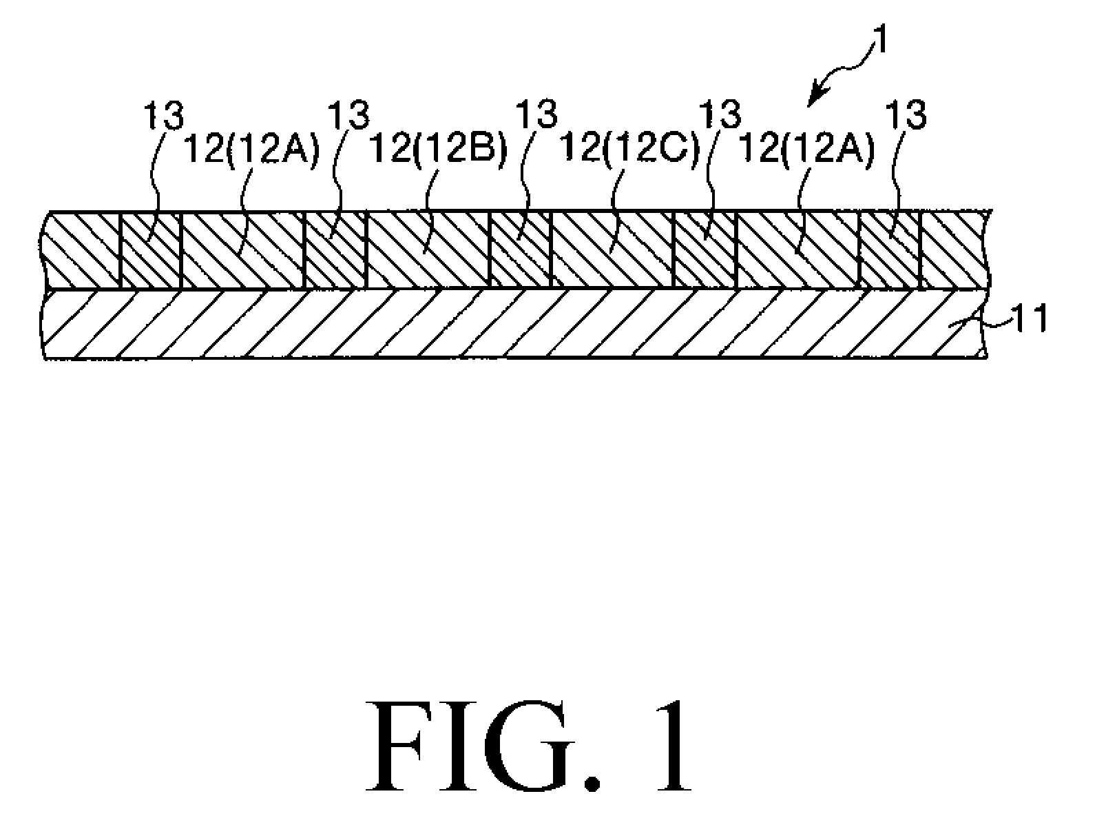
[0075]An ink 2 for use in a color filter 1 (hereinafter, simply referred to as “ink” on occasions) according to the present invention is an ink which is used for manufacturing a color filter (forming coloring parts of the color filter). In particular, the ink 2 according to the present invention is an ink which is used for manufacturing the color filter by an ink jet method.

[0076]The ink 2 is comprised of a coloring agent, a liquid medium in which the coloring agent is dissolved or dispersed and a resin material, and the like.

[0077]Coloring Agent

[0078]In general, a color filter 1 has a large number of coloring parts 12 having different colors (that is, three colors corresponding to red (R), green (G) and blue (B), namely RGB). Generally, a coloring agent is selected depending on the colors of the coloring parts to be formed. Examples of the coloring agent to constitute the ink 2 include various pigments and various dyes.

[0079]Examples of such various...

second embodiment

[0309]Hereinbelow, a description will be made with regard to a second embodiment. In this regard, it is to be noted that the description is made by focusing different points from the first embodiment, and the description for the common points with the first embodiment is omitted. The second embodiment is common with the first embodiment except for the correction data producing step.

[0310]In this correction data producing step of the second embodiment, first, an amount of an ink 2 ejected from each nozzle 25 per one ejecting operation is detected.

[0311]This detection is carried out, for example, by ejecting a droplet of the ink 2 from the nozzle 25 onto a glass substrate with one ejection operation and then measuring a volume of the one droplet of the ink 2 on the glass substrate by an optical method. Alternatively, the detection may be carried out by applying a droplet of the ink 2 onto a roll paper and then taking an image of the droplet of the ink 2 by a CCD camera 5 to measure a ...

third embodiment

[0315]Hereinbelow, a description will be made with regard to a third embodiment. In this regard, it is to be noted that the description is made by focusing different points from the first embodiment, and the description for the common points with the first embodiment is omitted. The third embodiment is common with the first embodiment except for further providing a driving voltage adjusting step.

[0316]In this third embodiment, prior to the correction data producing step, a driving voltage adjusting step which adjusts a driving voltage to be applied across the pair of the electrodes 124A and 124B (that is, to the piezo electric element (driving element) 124C) is carried out.

[0317]In this driving voltage adjusting step of the third embodiment, first, an amount of an ink 2 ejected from each nozzle 25 per one ejecting operation is detected.

[0318]This detection is carried out, for example, by ejecting a droplet of the ink 2 from the nozzle 25 onto a glass substrate with one ejection oper...


PUM

PropertyMeasurementUnit
Coloraaaaaaaaaa
Sizeaaaaaaaaaa

Abstract

A color filter manufacturing method includes supplying different colored ink to cells on a substrate from nozzles based on drawing pattern data; determining whether any droplet ejection apparatus part is washed or exchanged, or a color filter size is changed; and if so, producing correction data for correcting the drawing pattern data. The correction data is produced by preparing a test substrate having cells corresponding to the cells of the substrate; supplying ink to predetermined test cells; and detecting an ink amount supplied to each test cell. The correction data is then used to adjust the ink droplets supplied to the color filter substrate cells to a target amount. The drawing pattern data is then corrected with the produced correction data; and the ink is supplied to the substrate cells using the corrected drawing pattern data to manufacture the color filter.

Description

CROSS-REFERENCE TO RELATED APPLICATION[0001]This application claims priority to Japanese Patent Application No. 2007-302301 filed Nov. 21, 2007, which is hereby expressly incorporated by reference herein in its entirety.BACKGROUND[0002]1. Technical Field[0003]The present invention relates to a method of manufacturing a color filter, a color filter, an image display device and an electronic apparatus, and more particularly to a method of manufacturing a color filter, a color filter manufactured by the manufacturing method, an image display device provided with the color filter and an electronic apparatus provided with the image display device.[0004]2. Related Art[0005]Generally, a color filter is used in a liquid crystal display device (LCD) which can display an image composed of different colors.[0006]A conventional color filter has been manufactured using a so called “photolithography method”. The photolithography method is carried out by the following steps. First, a material cont...

Claims


Application Information

Patent Timeline
IPC IPC(8): G02B5/23B05D5/06
CPCG02B5/223G02B5/201
Inventor SANO, JUNICHI
Owner SEIKO EPSON CORP
Why Eureka
Try Eureka