Brightness adjustable keyboard illuminating module of electronic device

a technology of electronic devices and keyboards, applied in the field of illumination modules, can solve problems such as problems, and achieve the effect of achieving preferred lighting effects

Inactive Publication Date: 2009-05-21
MITAC TECH CORP
View PDF14 Cites 5 Cited by
  • Summary
  • Abstract
  • Description
  • Claims
  • Application Information

AI Technical Summary

Benefits of technology

[0008]Accordingly, the present invention provides a keyboard illuminating module of an electronic device, which uses a pulse width modulation (PWM) signal together with a low-cost voltage control circuit to adjust brightness of a light source output from the keyboard illuminating module, so as to achieve preferred lighting effects.

Problems solved by technology

However, the laptop user may still need to operate the computer while projecting the data onto a large screen when the environmental light is insufficient, it is possible that the required key cannot be found or the incorrect key is pressed, which is quite inconvenient.
Though the above designs can solve the lighting requirement problem when using the keyboard, but when the environment has different brightness conditions, preferable illumination effect can not be obtained if the keyboard is still illuminated with the same brightness light.
Therefore, it has become a problem need to be solved by researchers for providing a keyboard illuminating module that can adjust the brightness.

Method used


Image

  • Brightness adjustable keyboard illuminating module of electronic device
  • Brightness adjustable keyboard illuminating module of electronic device
  • Brightness adjustable keyboard illuminating module of electronic device

Examples


first embodiment

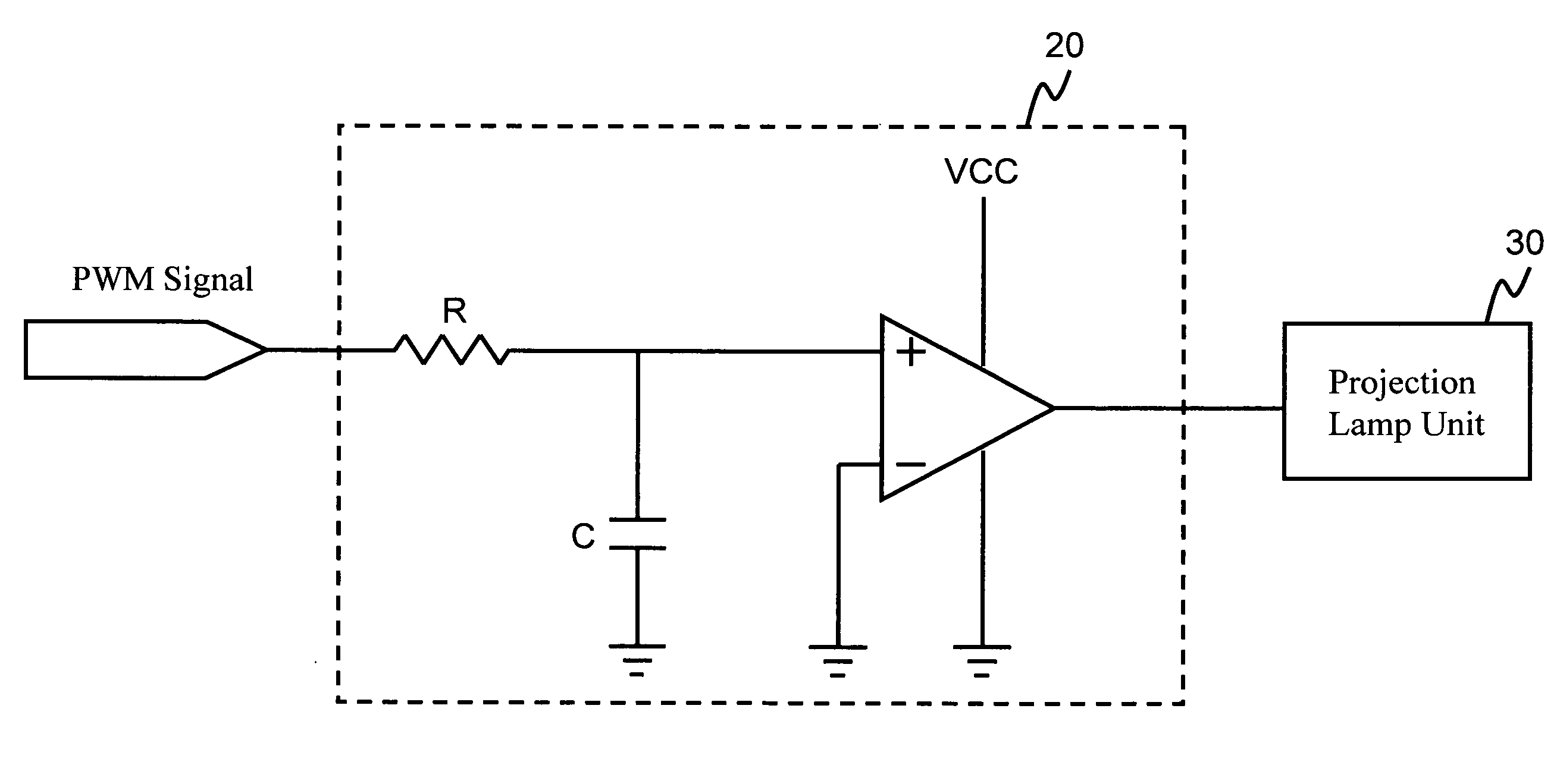
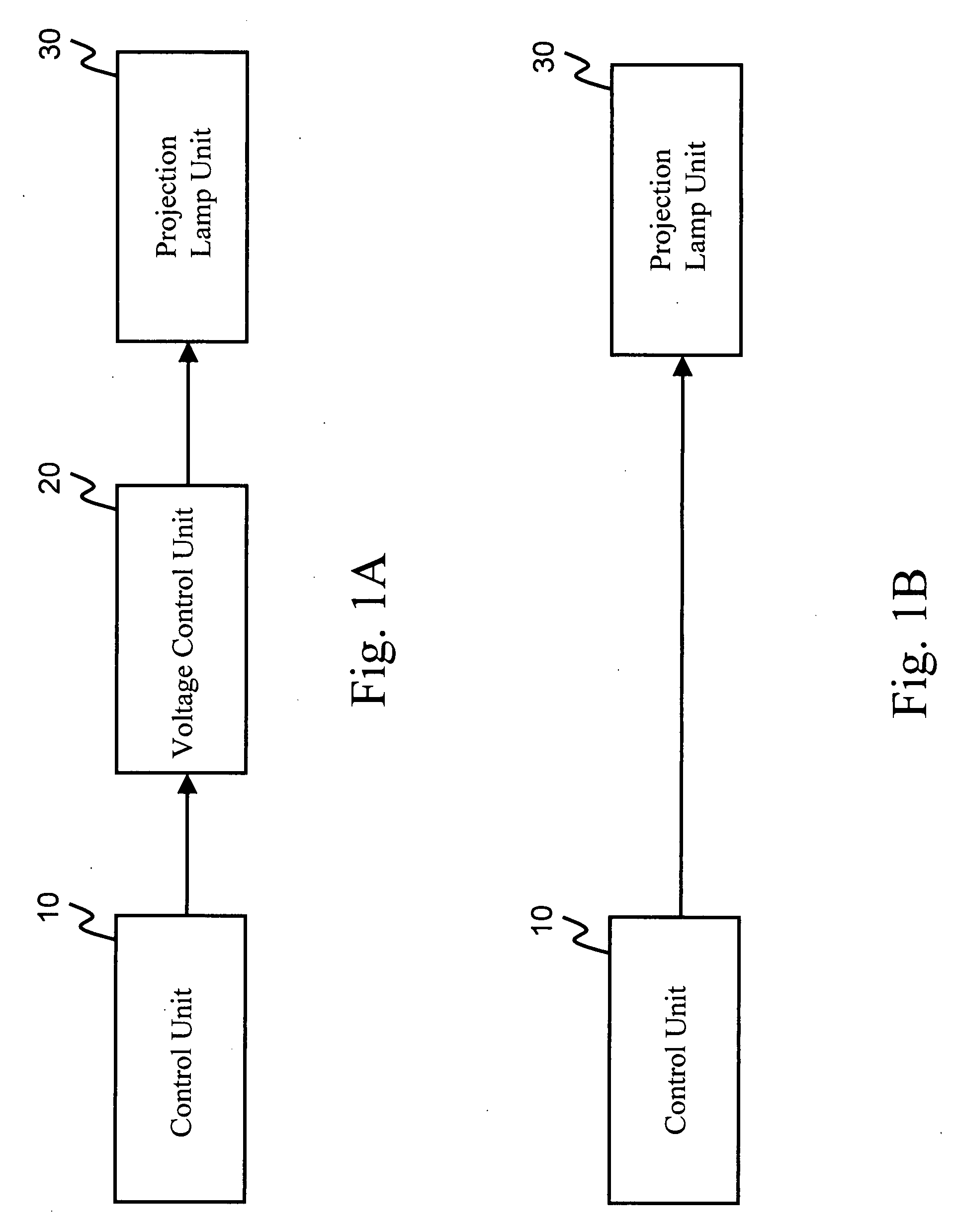
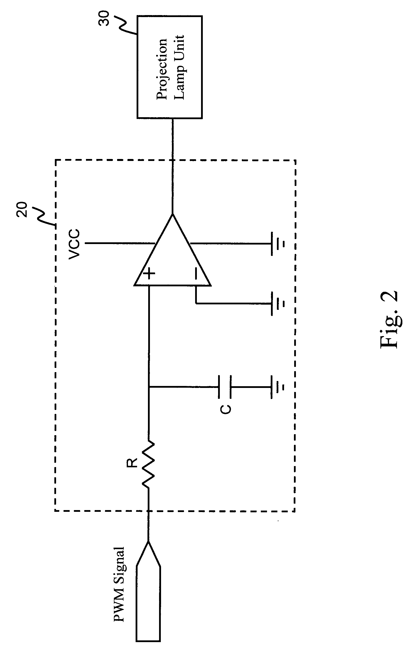
[0017]FIG. 1A is a system block diagram of the present invention. As shown in FIG. 1A, the brightness adjustable keyboard illuminating module of an electronic device of the present invention includes a controlling unit 10, a voltage regulating unit 20, and a projection lamp unit 30.

[0018]The controlling unit 10 is electrically connected to the voltage regulating unit 20, and receives a brightness adjusting command. The brightness adjusting command is, for example, sent from application software that offers a brightness adjusting function in an operating system, or generated by hardware circuits according to an operation of a user.

[0019]Then, the controlling unit 10 generates and outputs a pulse width modulation (PWM) signal according to the brightness adjusting command. The controlling unit 10 can be, for example, an embedded controller (EC), a keyboard controller (KBC), or a PWM integrated circuit (PWM IC).

[0020]In addition, the controlling unit 10 can be further connected to a cir...

second embodiment

[0024]FIG. 1B is a system block diagram of the present invention. Referring to FIG. 1B, the brightness adjustable keyboard illuminating module of the electronic device of the present invention includes a controlling unit 10 and a projection lamp unit 30.

[0025]The controlling unit 10 is electrically connected to the projection lamp unit 30, and receives a brightness adjusting data. The brightness adjusting data can be, for example, sent from an application that offers a brightness adjusting function in an operating system, or generated by hardware circuits according to a user's operation result. Then, the controlling unit 10 converts the brightness adjusting data into an analog driving signal and outputs the analog driving signal. The controlling unit 10 can be, for example, an embedded controller (EC), a keyboard controller (KBC), or a digital to analog converter (DAC) integrated circuit.

[0026]In addition, the controlling unit 10 can be further connected to a circuit having photonic...


PUM


Abstract

A brightness adjustable keyboard illuminating module of an electronic device includes a controlling unit, a voltage regulating unit, and a projection lamp unit. The controlling unit is used for receiving a brightness adjusting command to generate a pulse width modulation (PWM) signal according to the brightness adjusting command. The voltage regulating unit receives the PWM signal and regulates a voltage of an output driving signal according to a duty cycle of the PWM signal. The projection lamp unit receives the driving signal and projects light in response to the voltage of an output driving signal, to the keyboard of the electronic device.

Description

BACKGROUND OF THE INVENTION[0001]1. Field of the Invention[0002]The present invention relates to an illuminating module, and more particularly to a keyboard illuminating module of an electronic device.[0003]2. Related Art[0004]As the rapid development of computers, it has become an essential demand for modern people to carry computers along with them. In order to meet such a trend, computer manufacturers are making portable computers into even smaller ones, i.e., laptops with a size similar to books. A laptop has functions almost the same as that of the desktop computer, but can be placed into a suitcase or a bag that can be taken along, so as to satisfy the businessmen's requirements that he / she can use the computer anytime and anywhere.[0005]As the laptop is small and light, it is frequently used in meetings, symposiums, or presentations, for presenting data. Generally, the data to be presented are projected onto a large screen. However, the laptop user may still need to operate t...

Claims


Application Information

Patent Timeline
Patent Type & Authority Applications(United States)
IPC IPC(8): H05B37/02H01H9/00
CPCG06F3/0202H05B41/3921H05B33/0848H05B45/14
Inventor WANG, CHUN-CHI
Owner MITAC TECH CORP
Why Eureka
Try Eureka