Angular Contact Ball Bearing and Joint Assembly for a Robotic Arm

a robotic arm and ball bearing technology, applied in the field of angular contact ball bearings, can solve the problems of limiting the machining accuracy, ball wear and peeling, and complicated ball spin, so as to improve the wear resistance, and reduce the weight of the angular contact ball bearing

Inactive Publication Date: 2009-05-21
NTN CORP
View PDF9 Cites 20 Cited by
  • Summary
  • Abstract
  • Description
  • Claims
  • Application Information

AI Technical Summary

Problems solved by technology

Such spinning causes wear and peeling of the balls and raceways.
In particular, with the angular contact ball bearing disclosed in the above earlier patent application, because there is a limit to the machining accuracy of the balls and the above one of the raceways, and because each ball contacts the one of the raceways at two points, the balls tend to spin in a complicated manner.
In the angular contact ball bearing disclosed in the above earlier patent application, because the two contact points on the one of the raceways are offset to one axial side from the bearing centerline, lubricant cannot be easily supplied to the above two contact points compared to conventional bearings.

Method used


Image

  • Angular Contact Ball Bearing and Joint Assembly for a Robotic Arm
  • Angular Contact Ball Bearing and Joint Assembly for a Robotic Arm
  • Angular Contact Ball Bearing and Joint Assembly for a Robotic Arm

Examples


third embodiment

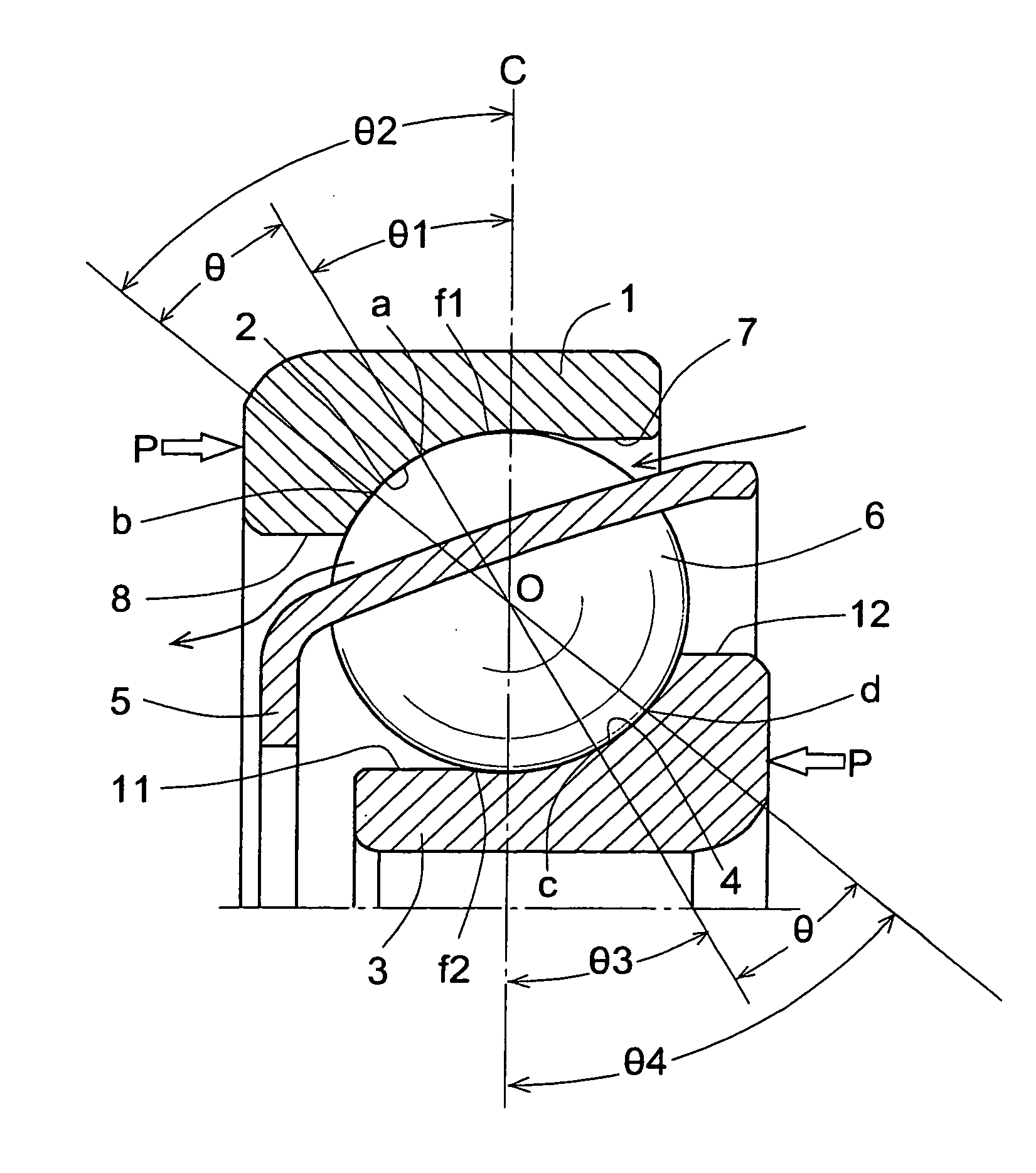
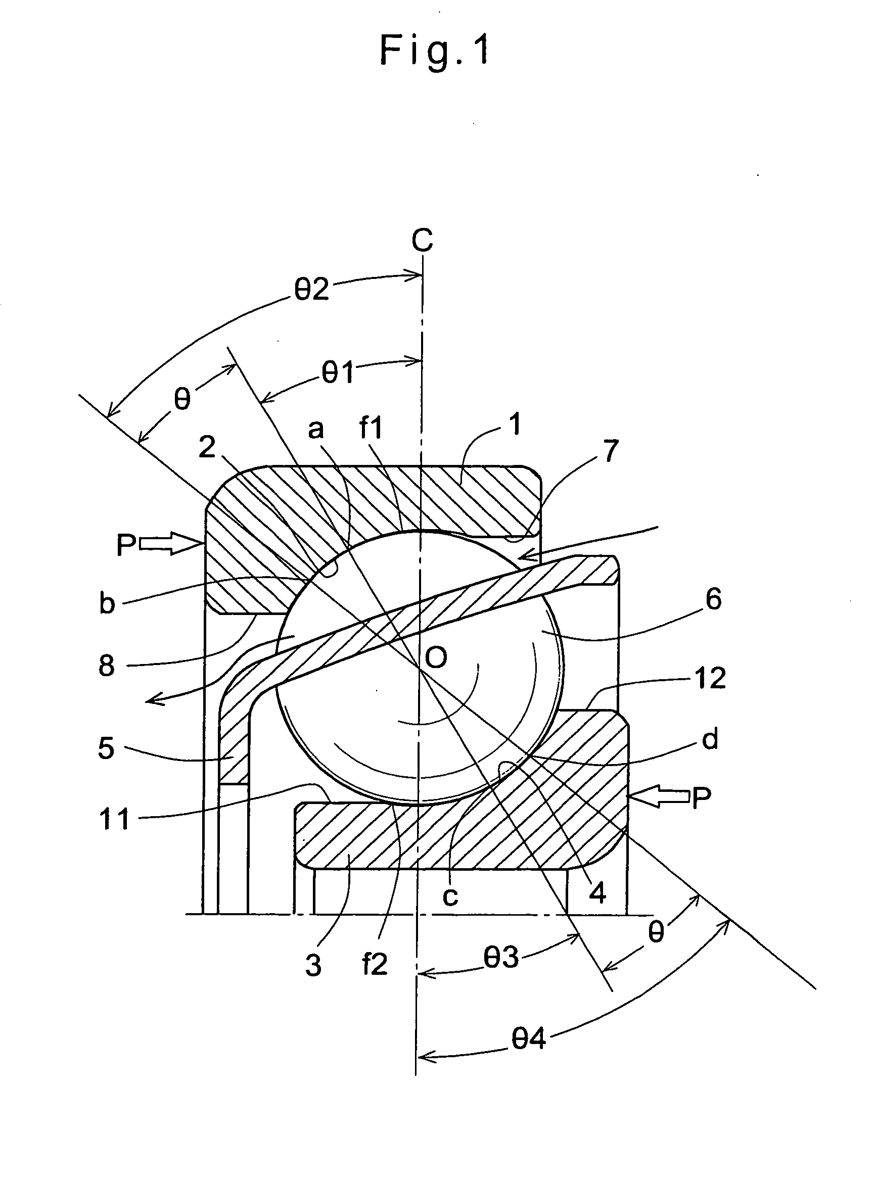
[0117]Each ball 6 of either of the first and second arrays 15 and 16 is in contact with each of the raceways 2 and 4 at two points, with the values of θ1 and θ3 set at 15° and the values of θ2 and θ4 set at 45°. Thus, the nominal contact angles in the first and second arrays 15 and 16 are both 30°. This determines the nominal lines of action. Because the angular contact ball bearing is of the face-to-face duplex structure, the nominal lines of action of the first and second arrays 15 and 16 intersect each other inside the bearing.

[0118]Lubricating oil supplied into the space between the outer rings 1 flows along the counter portion 7 into the first and second arrays 15 and 16. This is because the retainers 5 are arcuately curved. According to the structures of the retainers and the housing and the use environment, oil circulation paths and the lubricating method can be determined.

[0119]The fourth embodiment for achieving the first object is now described. The angular contact ball b...

sixth embodiment

[0130]The main bearing 45 is the angular contact ball bearing which is of the back-to-back duplex structure. The main bearing 45 includes outer rings 49 fitted in the drum 46, and inner rings 50 fitted on the case 41. That is, the main bearing 45 is disposed between the output shaft of the speed reducer (which comprises the ring gear 47 and the drum 46) and the driving side. A preload is applied to the main bearing 45.

[0131]The inner and outer rings of the main bearing 45 are offset from each other by a distance h such that the shoulder 51 of each inner ring 50 is located axially outside the counter portion 52 of the corresponding outer ring 49. This arrangement increases the spaces between the shoulders 51 and the counter portions 52, so that lubricating oil can more smoothly flow into the bearing.

[0132]Because the main bearing 45 has improved rigidity compared to conventional such bearings as mentioned above, it is possible to correspondingly reduce the wall thickness of the drum...

seventh embodiment

[0133]Now referring to FIGS. 10 and 11, description is made of the seventh embodiment for achieving the second objection.

[0134]As shown in FIG. 10, this bearing is an angular contact ball bearing comprising an outer ring 1′ having a raceway 2′, an inner ring 3′ having a raceway 4′, balls 6′ disposed between the raceways 2′ and 4′, and a retainer 5′ spacing the balls 6′ from each other at predetermined intervals.

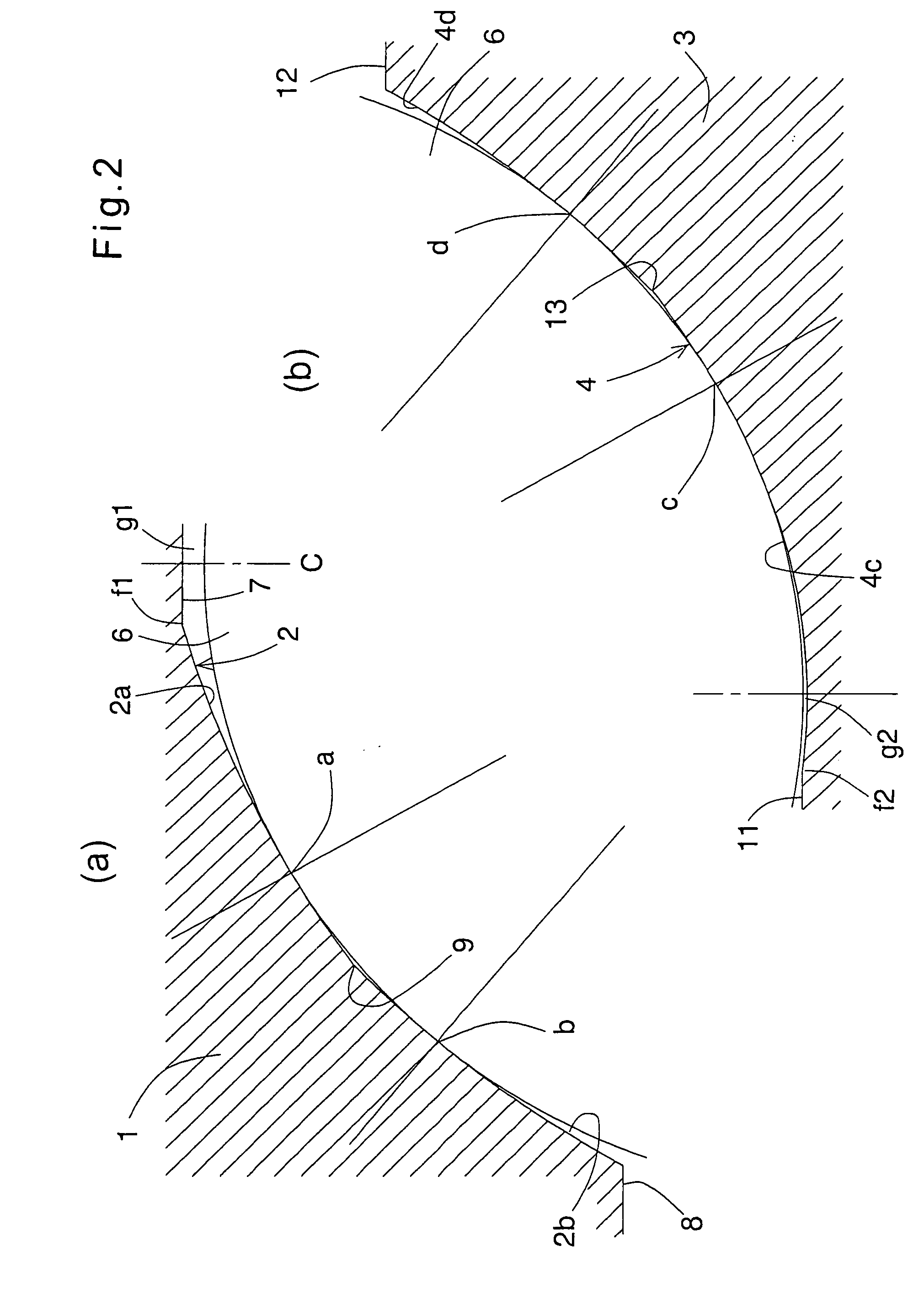
[0135]On the radially inner surface of the outer ring 1′, a large-diameter inner surface 7′ and a small-diameter inner surface 8′ are formed at both ends thereof. The raceway 2′, which is arcuate as a whole, is formed between the inner surfaces 7′ and 8′. As is apparent from FIG. 11(a), the raceway 2′ comprises two arch-shaped arcuate surfaces 2a′ and 2b′. Contact points a and b with each ball 6′ are formed on both sides of the abutment 9′ between the arcuate surfaces 2a′ and 2b′. In FIG. 10, the contact angle at the contact point a with respect to the bearing centerline C is...


PUM


Abstract

It is aimed to increase the rigidity of an angular contact ball bearing of the type in which each ball contacts at least one of the raceways at two points, improve the lubricating environment of the balls, reduce the weight of the bearing while maintaining wear resistance and rigidity of the balls, reduce the weight of the bearing while maintaining wear resistance of the balls, improve the radial rigidity and axial rigidity of the bearing in a balanced manner, or to supply a sufficient amount of lubricating oil into an internal area between the two contact points between each ball and the raceway.A counter portion 7 is formed. With each ball 6 in contact with the raceway at two points, a gap is present between the portion of the bearing ring at the bearing centerline C and each ball 6. The balls 6 may be ceramic balls. A coating for improving wear resistance may be applied to the balls. The contact angle of the contact point close to the bearing center line is set at 15 to 25°, while the contact angle of the contact point remote from the centerline C is set at 40 to 50°.

Description

TECHNICAL FIELD[0001]The present invention relates to an angular contact ball bearing, and particularly to one that is suitable for supporting a rotary shaft to which moment loads are applied at a low rotational speed.BACKGROUND ART[0002]Driving units of which the output shaft is rotated at a low speed not exceeding 100 rpm, such as sprocket driving units in construction machines and joint assemblies for robotic arms, include a driving source and a speed reducer. The output shaft of the speed reducer is rotatably supported through a main bearing disposed between the output shaft and the driving unit. The loading point of such a main bearing is located outside the bearing, so that moment loads are applied thereto. Thus, angular contact rolling bearings are used as such main bearings.[0003]With the above-described devices, it is desired to increase the rigidity of the main bearing against moment loads for accurate attitude control and positioning of the arm or machine.[0004]Convention...

Claims


Application Information

Patent Timeline
Patent Type & Authority Applications(United States)
IPC IPC(8): F16C33/58F16C33/32F16C33/66
CPCB25J9/108B25J19/0062F16C19/166F16C19/183F16C2240/76F16C19/505F16C2240/34F16C19/184F16C19/548F16C33/585F16C2240/30F16C19/16F16C33/32
Inventor HATTORI, JUNICHI
Owner NTN CORP
Why Eureka
Try Eureka