Light transmission device and method of setting light input break detection threshold value

a technology of light transmission device and threshold value, which is applied in the direction of multiplex communication, fault recovery arrangement, instruments, etc., can solve the problems of unnegligible amount of ase noise generated by these light amplifiers, inability to accurately detect light input break, and more ase noise accumulation

Inactive Publication Date: 2009-05-21
FUJITSU LTD
View PDF10 Cites 13 Cited by
  • Summary
  • Abstract
  • Description
  • Claims
  • Application Information

AI Technical Summary

Benefits of technology

[0021]According to an aspect of an embodiment, in a light transmission device for switching a light transmission path for receiving an optical signal from a currently used system to a backup system when the light level of light input from a light transmission path of a currently used system becomes substantially equal to or less than a light input break detection threshold value which serves as a reference for detecting a light input break. The light transmission device includes light level measuring means for measuring the light level of the light input from the light transmission path of the currently used system, and light input break detection threshold value setting means for detecting only the light level of accumulated noise of the light level measured by the light level measuring means and setting the detected light level as the light input break detection threshold value.

Problems solved by technology

However, recently, ASE noise, which is generated by these light amplifiers, is accumulated in an unnegligible amount in a light transmission path in which the ASE noise passes through these light amplifiers in multiple stages.
However, since ASE noise is generated in this light amplification, when a plurality of optical add and drop multiplexers (OADM) are connected to each other in multiple stages and used, accumulated ASE noise must be taken into consideration when a failure occurs in the network.
Accordingly, there is a case that a light input break may not be accurately detected even if a light input break actually occurs because the accumulation level of ASE noise exceeds the light input break detection threshold value due to accumulated ASE noise.
However, since the number of the amplifiers through which the light passes is increased by disposing the in-line amplifiers, more ASE noise is accumulated, and thus the accumulated ASE noise cannot be further ignored.
Thus, a problem also arises in that a prescribed switching time cannot be satisfied.

Method used


Image

  • Light transmission device and method of setting light input break detection threshold value
  • Light transmission device and method of setting light input break detection threshold value
  • Light transmission device and method of setting light input break detection threshold value

Examples


embodiment 1

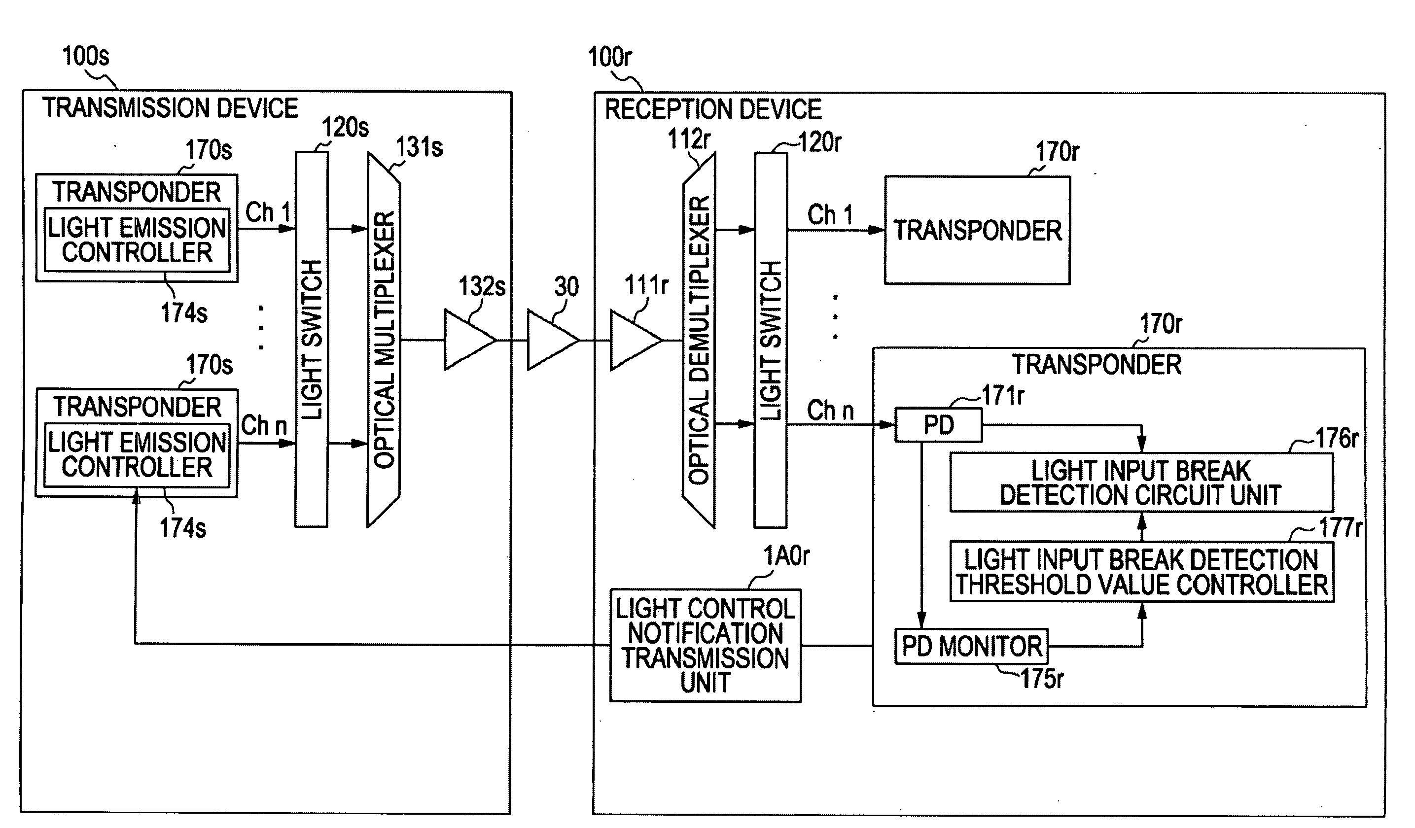
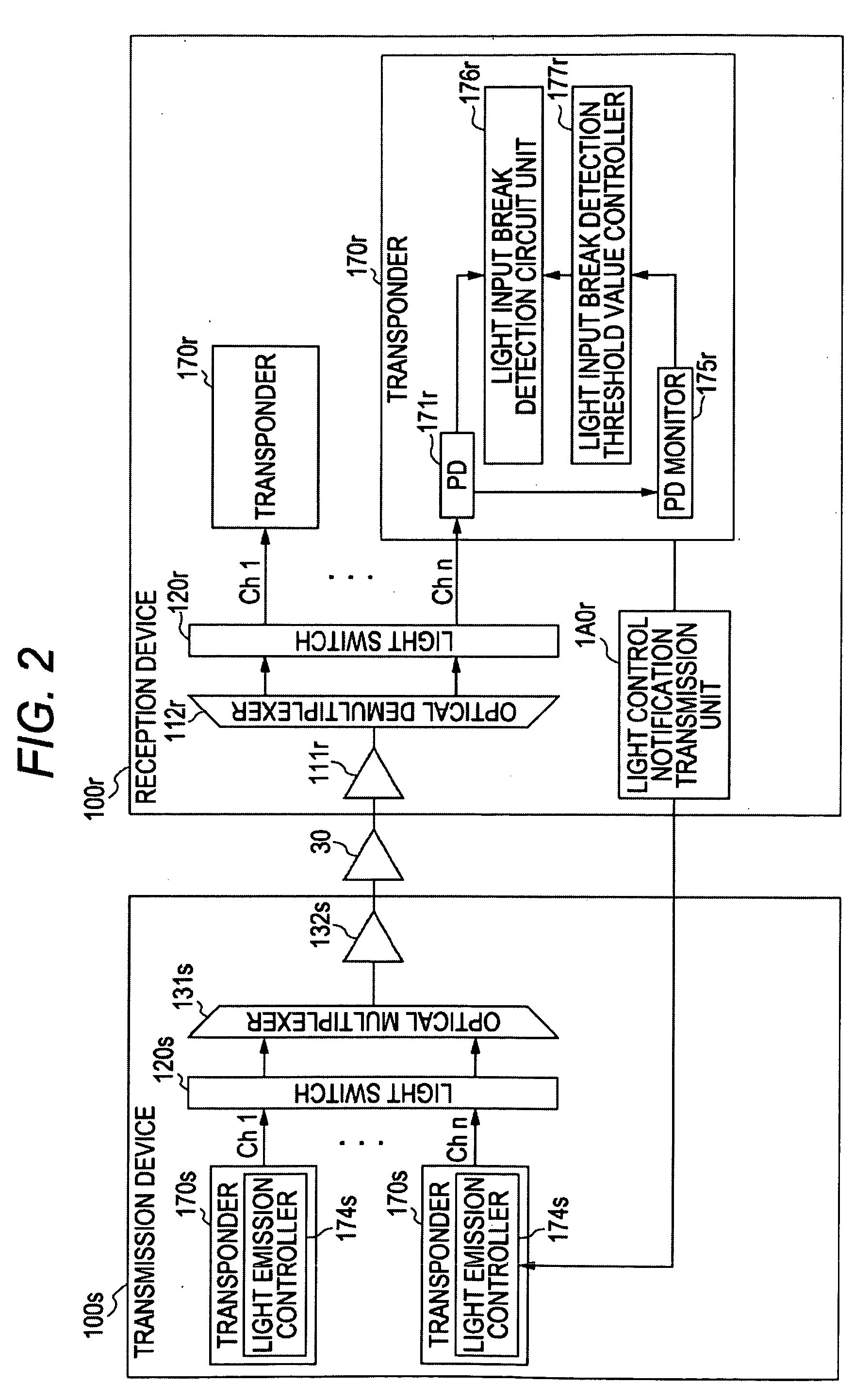
[0062]First, Embodiment 1 will be explained. In Embodiment 1, a reception device transmits a light shutdown notification to a transmission device connected thereto through an operation route to request it to stop outputting an optical signal. After the transmission device stops outputting the optical signal in response to the light shutdown notification transmitted thereof, the reception device sets a measured light level as a light input break detection threshold value.

[0063]FIG. 2 is a view illustrating the transmission device and the reception device according to Embodiment 1. Note that, to simplify the explanation, only the function units that are necessary to explain the feature of Embodiment 1 will be explained here. Also, the function units which achieve the same roles as those of the respective function units shown in FIG. 1 are denoted by the same reference numerals (“s” is added to the reference numerals on the transmission device side, and “r” is added to the reference nu...

embodiment 2

[0083]Next, Embodiment 2 will be explained. In Embodiment 2, a reception device removes the band, in which an optical signal is included, from the band of light input from an operation route, measures the light level of only accumulated noise from which the band of the optical signal is removed, and sets the measured light level as a light input break detection threshold value.

[0084]FIG. 4 is a view illustrating a transmission device and the reception device according to Embodiment 2. Note that, to simplify the explanation, only the function units that are necessary to explain the feature of Embodiment 2 will be explained here. Also, the function units that achieve the same roles as those of the respective function units described up to now are denoted by the same reference numerals, and the detailed explanation thereof is omitted.

[0085]As shown in FIG. 4, a transmission device 200s and a reception device 200r according to Embodiment 2 are connected to each other through an optical ...

embodiment 3

[0093]Next, Embodiment 3 will be explained. In Embodiment 3, a reception device measures the optical signal to noise ratio of light input from an operation route, calculates only the light level of only accumulated noise based on the measured optical signal to noise ratio, and sets the calculated light level as a light input break detection threshold value.

[0094]FIG. 6 is a view illustrating a transmission device and the reception device according to Embodiment 3. Note that, to simplify the explanation, only the function units that are necessary to explain the feature of Embodiment 3 will be shown here. Also, the function units that achieve the same roles as those of the respective function units shown up to now are denoted by the same reference numerals, and the detailed explanation thereof is omitted.

[0095]As shown in FIG. 6, a transmission device 300s and a reception device 300r according to Embodiment 3 are connected to each other through an optical ring network in which an in-l...


PUM


Abstract

According to an aspect of an embodiment, in a light transmission device for switching a light transmission path for receiving an optical signal from a currently used system to a backup system when the light level of light input from a light transmission path of a currently used system becomes substantially equal to or less than a light input break detection threshold value which serves as a reference for detecting a light input break. The light transmission device includes light level measuring means for measuring the light level of the light input from the light transmission path of the currently used system, and light input break detection threshold value setting means for detecting only the light level of accumulated noise of the light level measured by the light level measuring means and setting the detected light level as the light input break detection threshold value.

Description

CROSS-REFERENCE TO RELATED APPLICATIONS[0001]This application is based upon and claims the benefit of priority of the prior Japanese Application No. 2007-301758, filed on Nov. 21, 2007, the entire contents of which are incorporated herein by reference.BACKGROUND[0002]1. Field[0003]The embodiments discussed herein are related to a light transmission device and a method of setting a light input break detection threshold value for switching a light transmission path through which an optical signal is received from a currently used system to a backup system when the light level of light input from the light transmission path of the currently used system becomes substantially equal to or less than a light input break detection threshold value acting as a reference for detecting a light input break. More particularly, the embodiments relate to a light transmission device and a method of setting a light input break detection threshold value capable of automatically setting a proper light i...

Claims


Application Information

Patent Timeline
Patent Type & Authority Applications(United States)
IPC IPC(8): H04J14/00H04B10/03H01L31/02H04B1/74H04B10/032H04B10/07H04B10/077H04B10/079H04B10/27H04B10/275H04B10/294H04B10/299H04J14/02
CPCH04B10/07955H04B2210/08H04J14/0221H04Q2011/0083H04J14/0294H04Q11/0062H04Q2011/0081H04J14/0283
Inventor OOHASHI, MASAHIROSAKANE, YUICHIROSHIMADA, YUJIYOSHII, HIROMU
Owner FUJITSU LTD
Why Eureka
Try Eureka