Catheter placement device

a catheter and placement device technology, applied in the direction of catheters, intravenous devices, guide needles, etc., can solve the problems of increasing material expenditure and total device cost, reducing the ability of one-handed device control, and reducing so as to avoid catheter bleeding, improve the observation of flash chambers, and improve the effect of observation

Inactive Publication Date: 2009-05-21
POPOV
View PDF10 Cites 106 Cited by
  • Summary
  • Abstract
  • Description
  • Claims
  • Application Information

AI Technical Summary

Benefits of technology

[0021]The catheter placement device includes a catheter cap for occluding a proximal opening of the catheter hub after the device transition into the protected position and disconnecting the catheter introducer from the catheter. The catheter cap is detachably positioned on the catheter introducer so that, after the needle distal sharp tip protection, the catheter cap is accessible for occluding the catheter hub proximal opening without previous detachment of the catheter cap from the catheter introducer. The catheter cap has a conical obturator and is positioned at the holder proximal end so that the conical obturator is directed proximally and there is a mounting means allowing mounting / detaching the catheter cap on / from the holder. The presence of the catheter cap in the catheter placement device allows the catheter occlusion immediately after the catheter emplacement and needle withdrawal thereby avoiding the catheter bleeding.
[0022]The guard carrier in the short length position is located above the flash chamber and is provided with a window to improve an observation of the flash chamber. Moreover, the retracting spring in the initial position is disposed proximally of the distal portion of the flash chamber thereby also improving the flash chamber observation.

Problems solved by technology

The disadvantage of the device is the restricted capability of the one-handed device control because the elongated stem is disposed within the receptacle and inaccessible for pushing by the fingers of user's hand holding the device.
Another disadvantage is the considerable length of the receptacle and the sprig due to the necessity to hose the all needle inside of the receptacle to protect the needle sharp point.
This leads to the inconvenience in the device holding by user's hand, heightens the material expenditure and total device cost, increases the package and shipping costs.
Another disadvantage is the presence of a substantial friction between the elongated stem and the needle hub during the catheter placement caused with the spring action.
Besides, this friction worsens the device reliability creating the capability of the detail jamming.
Another disadvantage is the relative complex device design caused with the disposition of the elongated stem within the receptacle, using the complicated design of the coupling appliance and carrying out the deepening within the receptacle for the engagement of the stopping member.
Another disadvantage is the worsened observation of the flash chamber due to the spring disposition over the flash chamber.
Another disadvantage is the impossibility of sufficient quick occlusion of the catheter opening after the catheter emplacement and the needle withdrawal leading to bleeding.

Method used


Image

  • Catheter placement device
  • Catheter placement device
  • Catheter placement device

Examples


Embodiment Construction

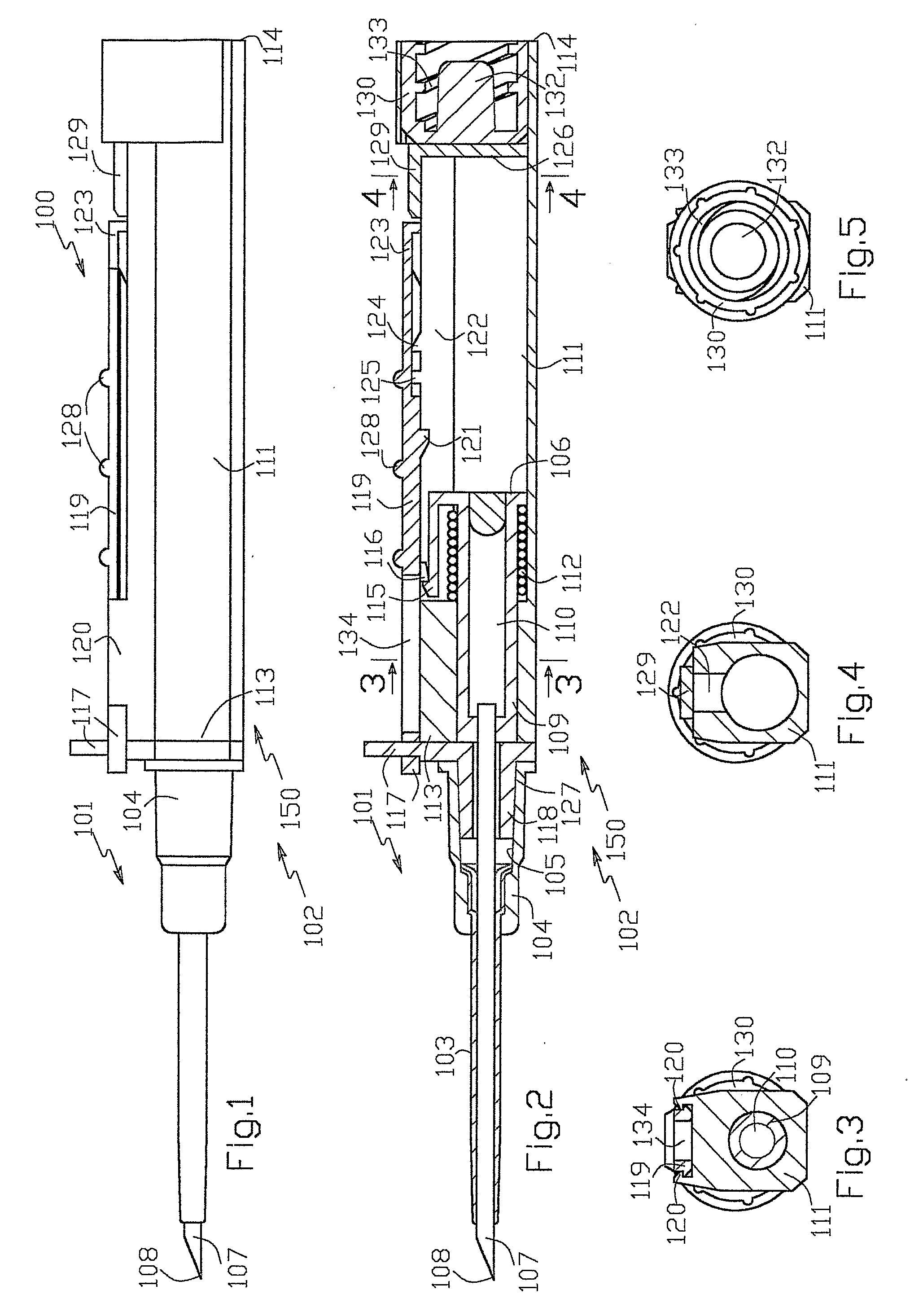
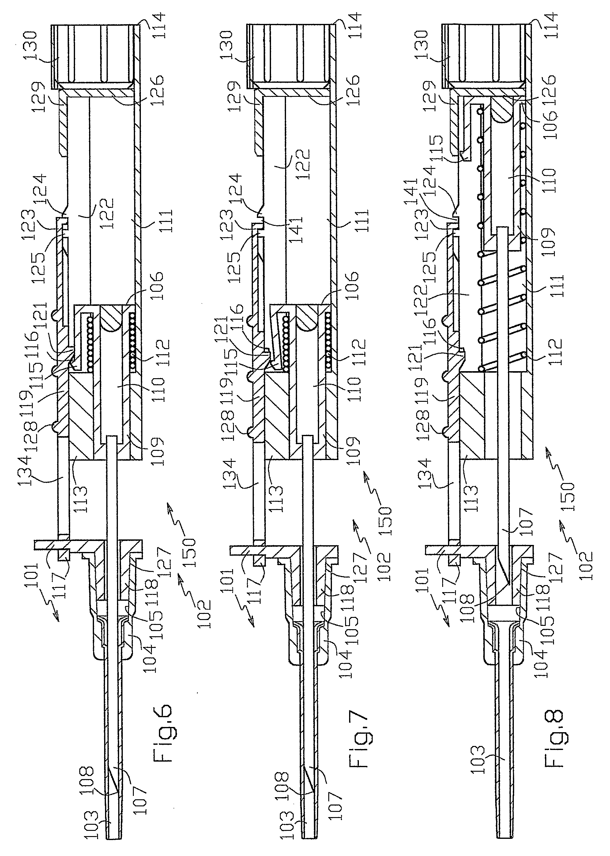
[0044]The detailed description of the present invention is offered with the references made to the enclosed drawings in FIGS. 1 to 19.

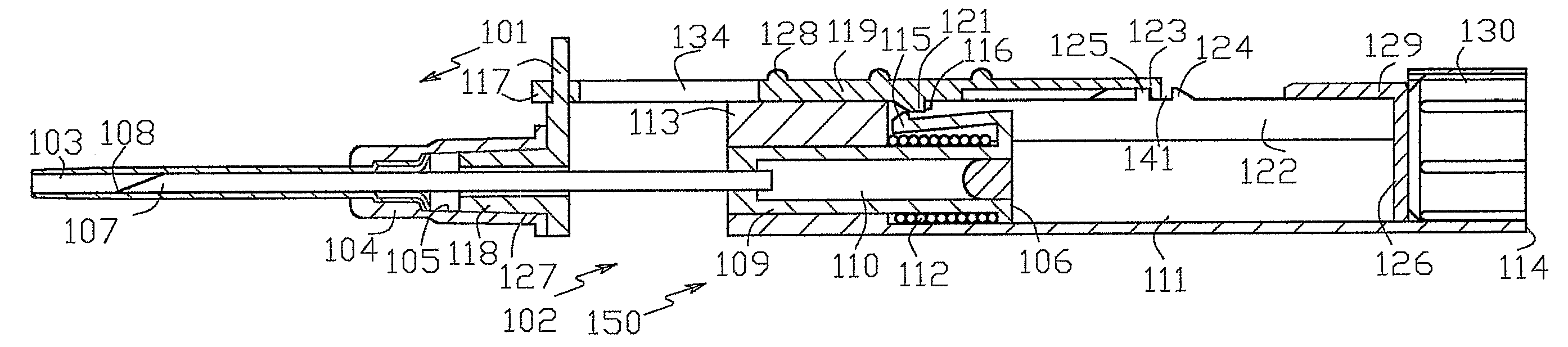
[0045]FIGS. 1 to 12 show catheter placement device 100 comprising catheter 101 and catheter introducer 102. Catheter 101 has axial through channel 103 and catheter hub 104 with female connector 105. Catheter introducer 102 has needle unit 106 and telescopic protector 135. Telescopic protector 150 has hollow elongated holder 111 and guard unit 117 including guard 118 and telescoping guard carrier 119 whereon guard 118 is located. Guard carrier 119 is made in the form of an elongated bar slidably disposed in guide 120 formed by the elements of holder 111. Needle unit 106 comprises needle 107 with sharpened tip 108 and needle hub 109, which is located at a needle proximal end and includes flash chamber 110. Needle hub 109 is movably hosed in holder 111. Retracting spring 112 disposed in holder 111 between the elements of needle hub 109 and holder 111 ada...


PUM


Abstract

Abstract A catheter placement device (see FIG. 2) includes a needle unit, which in an initial position is releasably engaged with a housing distal end and has a sharp needle passing through a catheter and protruding distally of it. There is also a telescopic protector including guard unit, which is sliding in a housing guide. After inserting the needle into patient's vein, operator one-handedly pushes the guard unit distally, thereby emplacing the catheter, displacing the protector into a full length position and locking therein, and passively disengaging the needle unit from the hosing by a trigger cam located on the guard unit. As a result, a retracting spring moves a needle into retracted position, wherein it is protected from any contact with personal. Then, operator disconnects the guard from the catheter, turns the housing and occludes the catheter entrance with a cap, which was detachably mounted on the housing.

Description

BACKGROUND OF THE INVENTION[0001]1. Field of the Invention[0002]The present invention relates to intravenous catheter placement devices, which employ a sharp needle to introduce and emplace an intravenous catheter into a blood vessel of a patient, specifically, to the devices wherein the needle is retracted into a protected position after catheter emplacement to prevent the user from accidental pricking by contaminated needle.[0003]2. Prior Art of the Invention[0004]Nowadays the protection of the contaminated needle sharp point from contact with personnel after the catheter emplacement is one of the main demands to the intravenous catheter placement devices. In this connection, the many modern devices provide the needle sharp point protection carried out as an alienable part of the general process of the catheter placement. Specifically, U.S. Pat. No. 5,573,510 “Safety intravenous catheter assembly with automatically retractable needle” discloses one of such devices. It includes a s...

Claims


Application Information

Patent Timeline
Patent Type & Authority Applications(United States)
IPC IPC(8): A61M25/06
CPCA61B17/3415A61M5/3232A61M25/0631A61M25/0606A61M25/0625A61M25/01
Inventor POPOV
Owner POPOV
Why Eureka
Try Eureka