Profiled rail system

a profiled rail and rail system technology, applied in the direction of resiliently mounted floors, flooring, roofing, etc., can solve the problem of not being able to produce the necessary dimensional accuracy, and achieve the effect of wide application, wide adaptability of the profiled rail system, and cost-effective production

Active Publication Date: 2009-05-28
HERM FRIEDR KUENNE GMBH & CO
View PDF12 Cites 5 Cited by
  • Summary
  • Abstract
  • Description
  • Claims
  • Application Information

AI Technical Summary

Benefits of technology

[0010]The profiled rail system in accordance with the invention is used to bridge expansion joints, cavities and / or as the edging of floor coverings. Particularly in floor coverings made of natural materials such as wood, consideration must be given to an expansion and shrinkage of the floor covering. For this purpose, expansion joints are left between the floor coverings. Moreover, for the same reason, the floor coverings are distanced from the walls in order, here too, to realize expansion joints. For this purpose, the profiled rail system has at least one web aligned substantially parallel to the floor covering, which web engages displaceably in a pocket. In this way, the profiled rail system is telescopable and can thus be adjusted to the expansions and shrinkages of the floor covering. In order to obtain a wide applicability for this profiled rail system, it is desirable to obtain as great a telescopability as possible. For this, the web would need to be shaped correspondingly long and the pocket correspondingly deep to allow even wide expansion joints and cavities to be reliably covered. Since these profiled rails are generally extruded, it is not however possible to produce a deep and flat pocket with the necessary dimensional accuracy. In order to solve this problem, the pocket of the profiled rail system is configured in two parts. The pocket consists, on the one hand, of a cover plate overlapping the web and, on the other hand, of a base plate underlapping the web. It is here envisaged that the cover plate is provided in a first part and the base plate in a second part. A deep recess in the profiled rail is thus no longer necessary, with the result that this can be very easily moulded. In this way, the depth of the pocket is basically unlimited. In order to hold the two parts securely together, holding means are provided, which join the two parts together.
[0017]It is advantageous if the floor covering is formed from floor covering elements, which can be held together in a click-in manner by undercut tongue and groove profilings. This produces a low complexity of assembly for laying of a floor covering. In order also to keep the complexity of laying the profiled rail system as low as possible, this is provided with undercut tongue and groove profilings to fit the floor covering elements. In these profilings, the floor coverings can be clicked appropriately in place. The mounting of the profiled rail system on the floor covering elements is here effected directly on the end face, so that an overlapping of the floor covering by the profiled rail system is not necessary. A continuous covering is thereby obtained, which, even in the region of the expansion joint, has a sufficiently firm connection. For the assembly of the profiled rail system, the profiled rails and / or the floor covering elements are tilted slightly and then the tongue is forced into the opposite groove. The assembly of the profiled rail system is essentially no different from the laying of the floor covering elements. This makes the laying of the total floor covering considerably easier and can thus be carried out without difficulty even by untrained persons. In particular, the need to align the profiled rail system to the expansion joint is eliminated. As a result of the click connection between the floor covering elements and the profiled rail, a correct mutual alignment of the two parts is automatically obtained. The fact that the floor covering elements are not overlapped by the profiled rail system also reduces the risk of tripping.

Problems solved by technology

Since these profiled rails are generally extruded, it is not however possible to produce a deep and flat pocket with the necessary dimensional accuracy.

Method used


Image

  • Profiled rail system
  • Profiled rail system
  • Profiled rail system

Examples


first embodiment

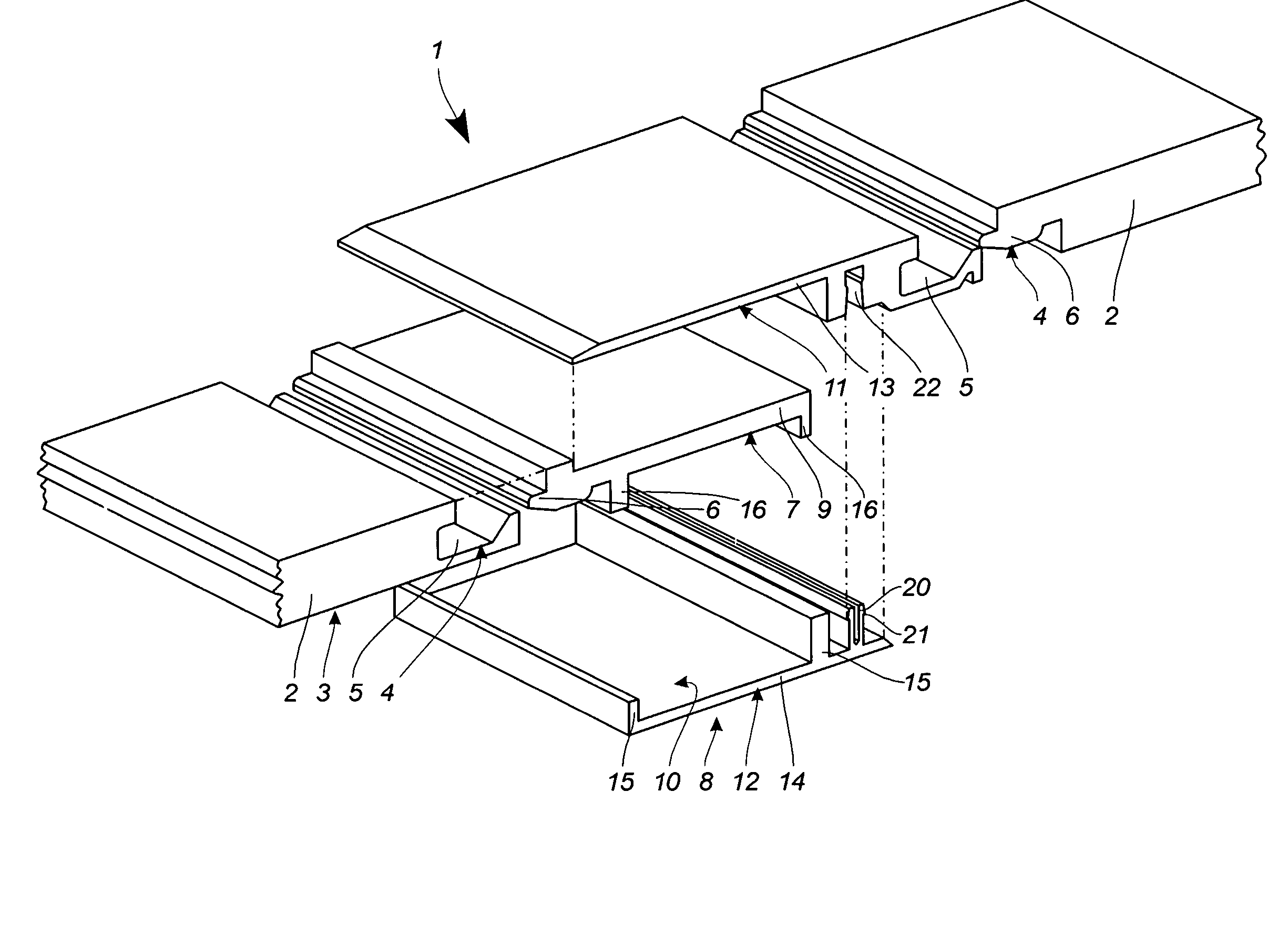
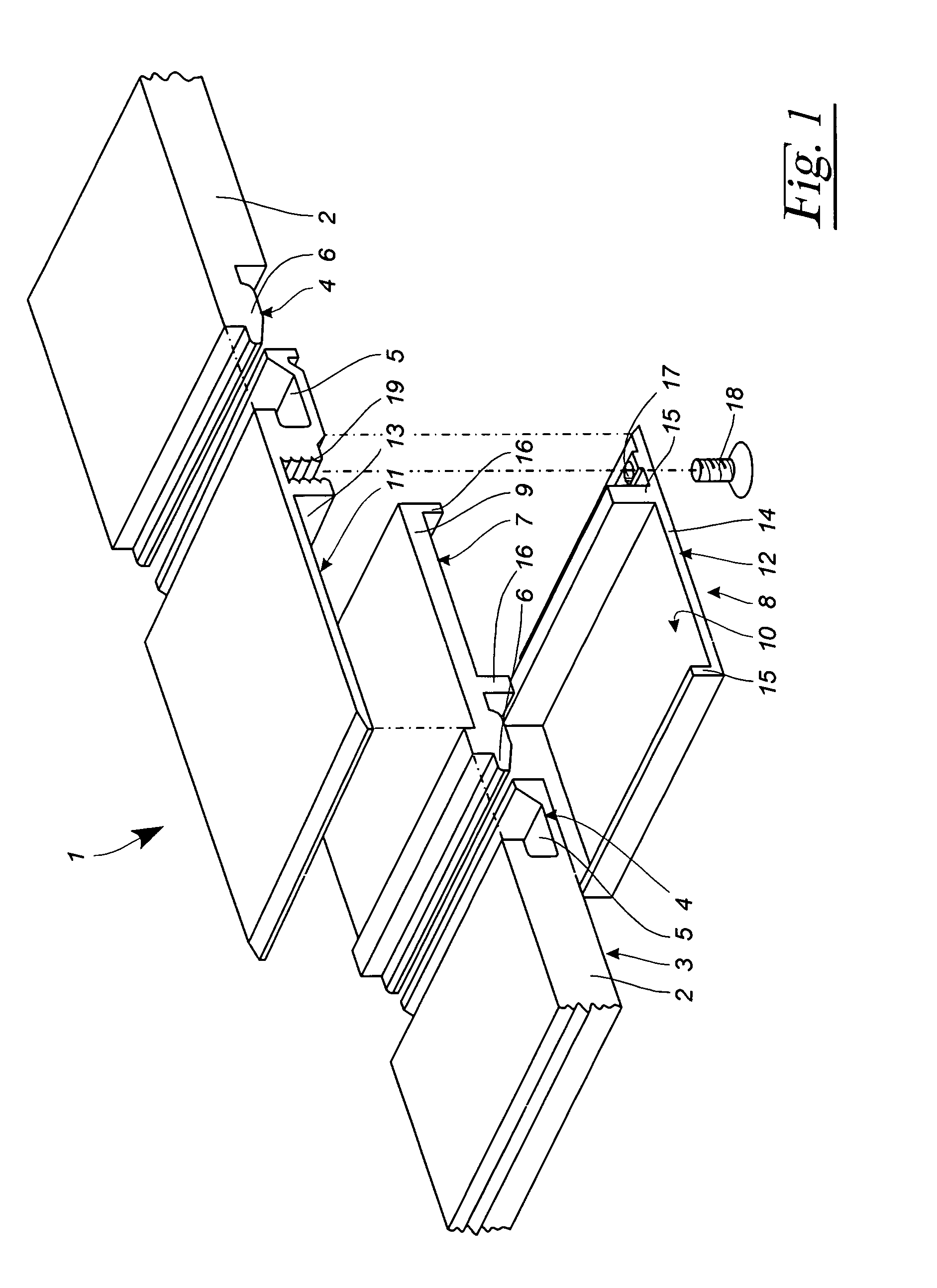
[0023]FIG. 1 shows a perspective exploded representation of a profiled rail system 1 having adjacent floor covering elements 2, which form a floor covering 3.

[0024]The floor covering element 2 has on the end face a tongue and groove profiling 4, which is formed, on the one hand, by an undercut groove 5 and, on the other hand, by an undercut tongue 6. By slightly angling a floor covering element 2, and then inserting the tongue 6 into the groove 5 and tilting the angled floor covering element 2 back into the horizontal position, the individual floor covering elements 2 can be clicked together. This allows particularly simple assembly of the floor covering 3, so that this can be laid even by untrained persons.

[0025]The profiled rail system 1 has respectively on the end face a groove 5 and tongue 6, which are shaped in accordance with the grooves 5 and tongues 6 of the floor covering elements 2. In this way, the profiled rail system 1 can be clicked together in the same way as the floo...

second embodiment

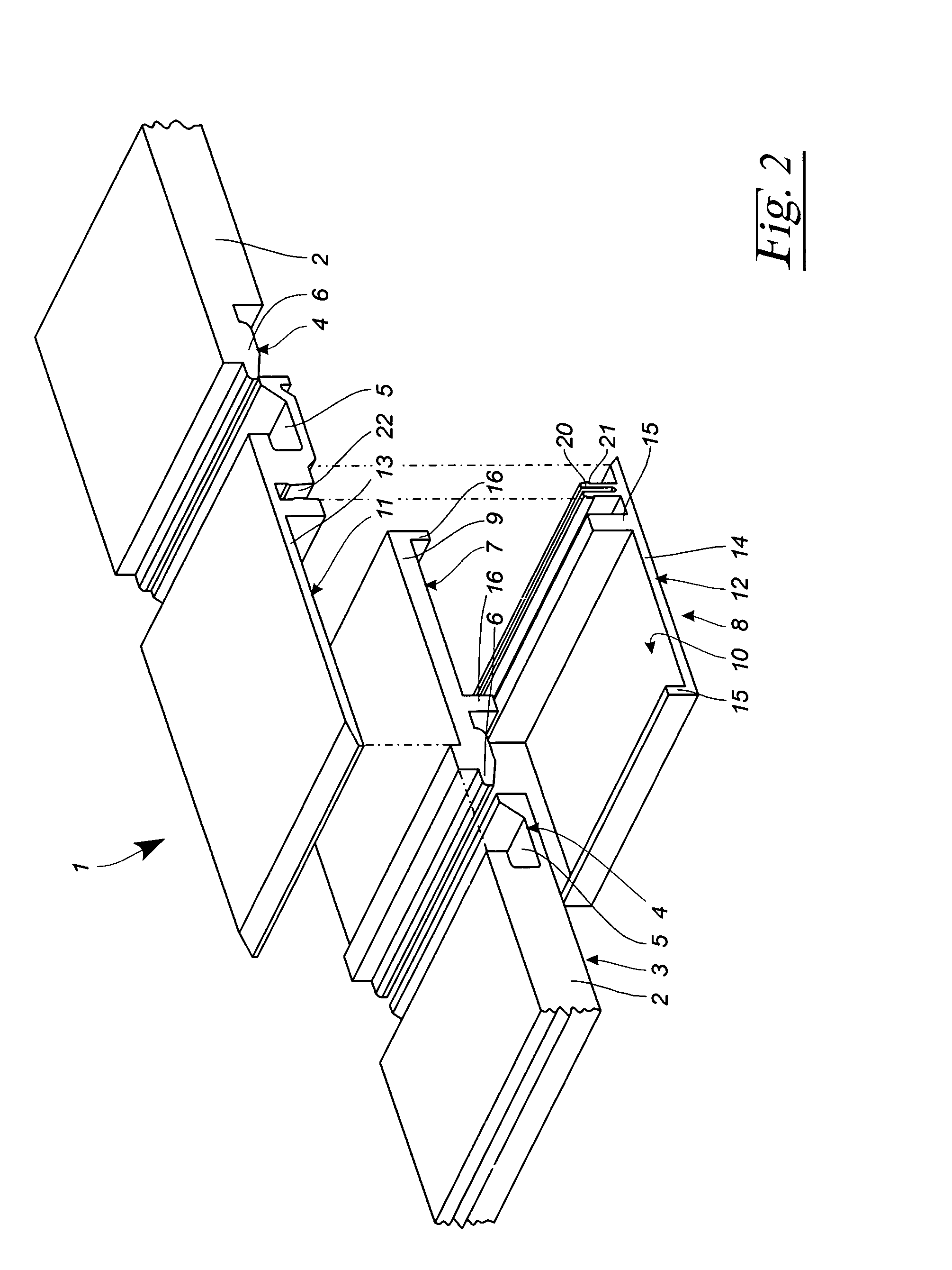
[0030]FIG. 2 shows the profiled rail system 1 according to FIG. 1, wherein the same reference symbols designate the same parts. Below, only the differences relative to the embodiment according to FIG. 1 are discussed.

[0031]For the fixing together of the parts 11, 12, in the embodiment according to FIG. 2 a screw connection is dispensed with. Instead, the second part 12 has two vertically upwardly directed webs 20, which are provided on the outside with respectively at least one undercut 21. The webs 20 engage in a likewise undercut receptacle 22 in the first part 11, which is configured to fit the webs 20.

[0032]For the assembly of the profiled rail system 1, the web part 7 is first placed into the pocket 10 of the second part 12. Then the first part 11 is pressed onto the second part 12 such that the webs 20 engage in the receptacle 22. When the parts 11, 12 are pressed together one against the other, the two webs 20 of the second part 12 are bent together, this deformation being re...


PUM


Abstract

A Profiled rail system (1) serves for bridging expansion joints, cavities and as an edging of floor coverings(3). Said profiled rail system (1) has at least one web (9) aligned substantially parallel to said floor covering (3), which web (9) engages displaceably in a pocket (10). Said pocket (10) is formed by a cover plate (13) overlapping said web (9) and a base plate (14) underlapping said web (9). Said pocket (10) being configured in at least two parts (11, 12). A first part (11) forming said cover plate (13) and a second part (12) forming said base plate(14). Said first (11) and second part (12) are held together by holding means (18, 20). In a first embodiment said holding means (18, 20) contain at least one undercut web (20) for achieving a click connection. In a second embodiment said holding means (18, 20) contain at least one screw (18).

Description

CROSS-REFERENCE TO RELATED APPLICATIONS[0001]Not ApplicableSTATEMENT REGARDING FEDERALLY SPONSORED RESEARCH OR DEVELOPMENT[0002]Not ApplicableREFERENCE TO A “SEQUENCE LISTING”, A TABLE, OR A COMPUTER PROGRAM LISTING APPENDIX SUBMITTED ON COMPACT DISC[0003]Not ApplicableBACKGROUND OF THE INVENTION[0004]1. Field of the Invention[0005]The invention relates to a profiled rail system for bridging expansion joints, cavities and / or as the edging of floor coverings.[0006]2. Description of Prior Art Including Information Disclosed Under 37 CFR 1.97 and 1.98[0007]From DE 20 2005 020 074 A1, a profiled rail system of the generic type is known. It essentially consists of two profiles, into which floor covering elements can be clicked in place on the end side. Both profiles are mutually telescopable. For this purpose, one of the profiles has a web aligned parallel to the floor covering, which web engages in a pocket of the opposite profile. This profiled rail system has proved itself in practice...

Claims


Application Information

Patent Timeline
Patent Type & Authority Applications(United States)
IPC IPC(8): E04B1/68
CPCE04F15/02005E04F19/061E04F2201/0153E04F19/065E04F19/062E04F15/02044E04F2015/02122
Inventor SONDERMANN, FRANK
Owner HERM FRIEDR KUENNE GMBH & CO
Why Eureka
Try Eureka