Robot Equipped with a Gyro and Gyro Calibration Apparatus, Program, and Method

a technology of gyro and calibration apparatus, applied in the field of robots equipped with gyro and gyro calibration apparatus, program and method, can solve the problems of difficult short-travel-purpose mobile robots to use the gps method, laborious and inconvenient technology, and relatively expensive position detection camera and image recognition technology, etc., to achieve the effect of easy measurement of position or orientation

Inactive Publication Date: 2009-05-28
TOYOTA JIDOSHA KK
View PDF3 Cites 35 Cited by
  • Summary
  • Abstract
  • Description
  • Claims
  • Application Information

AI Technical Summary

Benefits of technology

[0030]As described above, according to the gyro calibration apparatus, in a robot having a gyro, a gyro calibration program, and a gyro calibration method of the present invention, noises are suppressed during the cali

Problems solved by technology

However, it is difficult for the short-travel-purpose mobile robot to use the GPS method and its calibration method described in JP-A-07-286858.
Generally, however, the technology of the position detection camera and image recognition is relatively expensive and requires sufficient lighting.
Thus, this technology is laborious and inconvenient.
While the gyro used for this purpose provides a high accuracy, it is easily influenced by or interfered with mechanical disturbances

Method used


Image

  • Robot Equipped with a Gyro and Gyro Calibration Apparatus, Program, and Method
  • Robot Equipped with a Gyro and Gyro Calibration Apparatus, Program, and Method
  • Robot Equipped with a Gyro and Gyro Calibration Apparatus, Program, and Method

Examples


Embodiment Construction

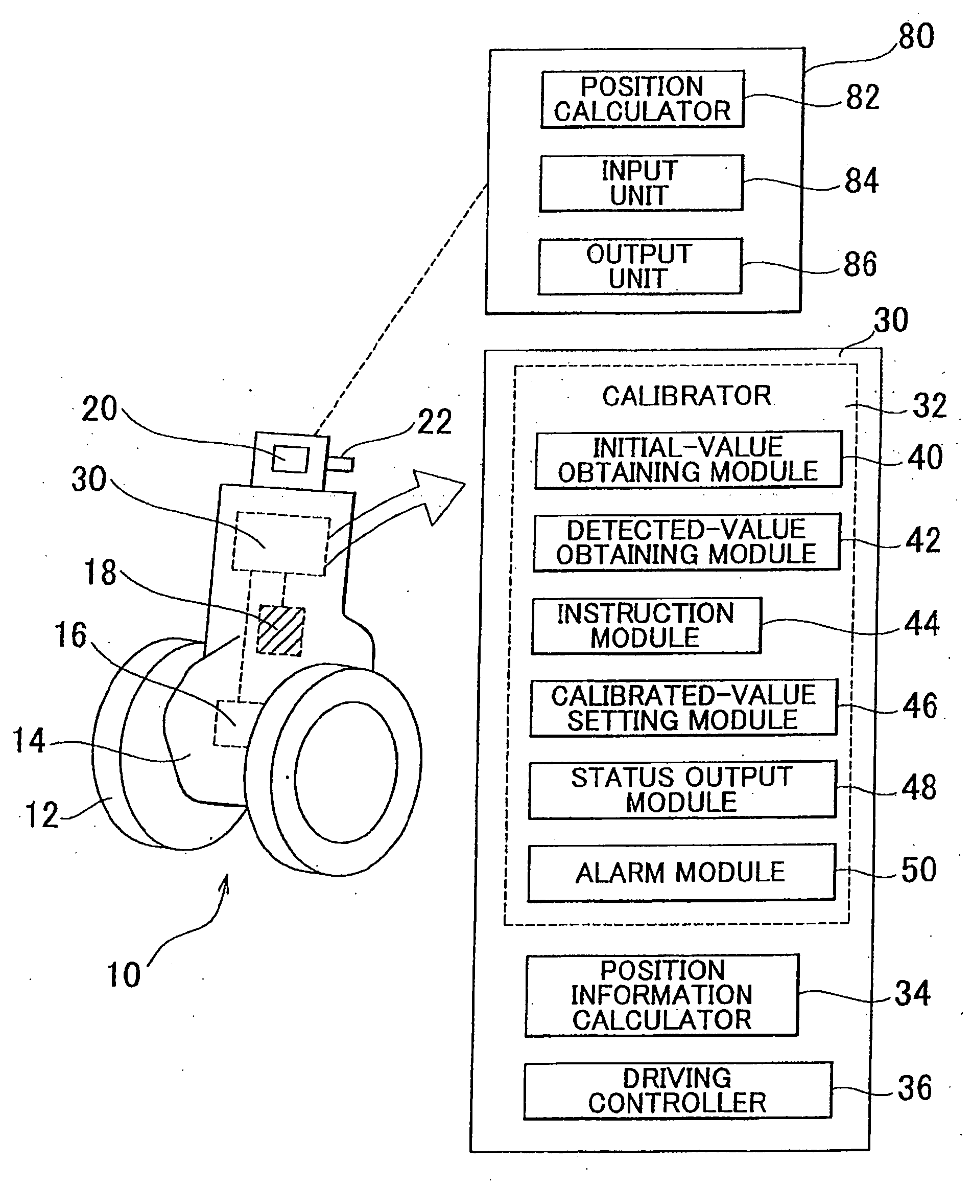
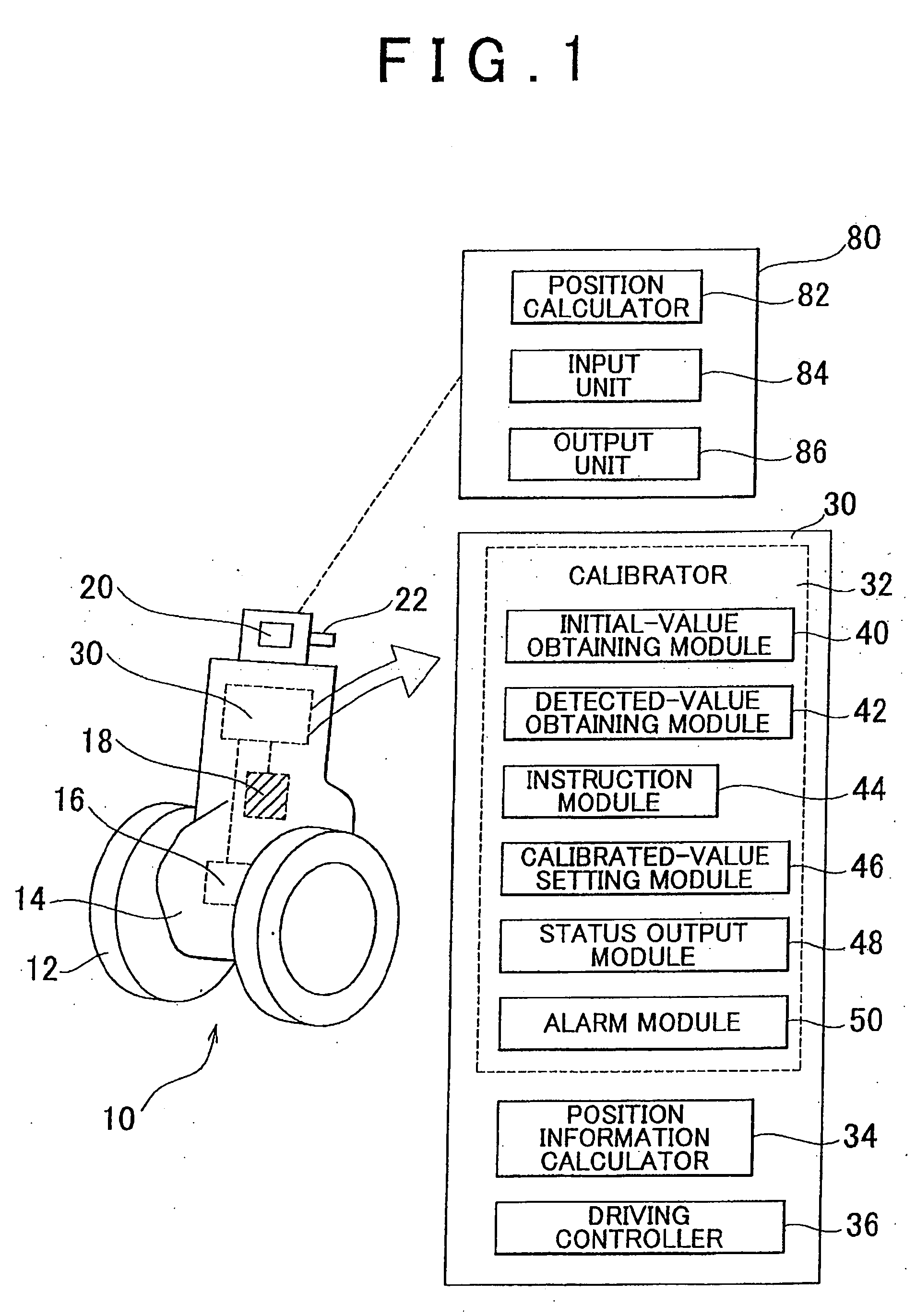
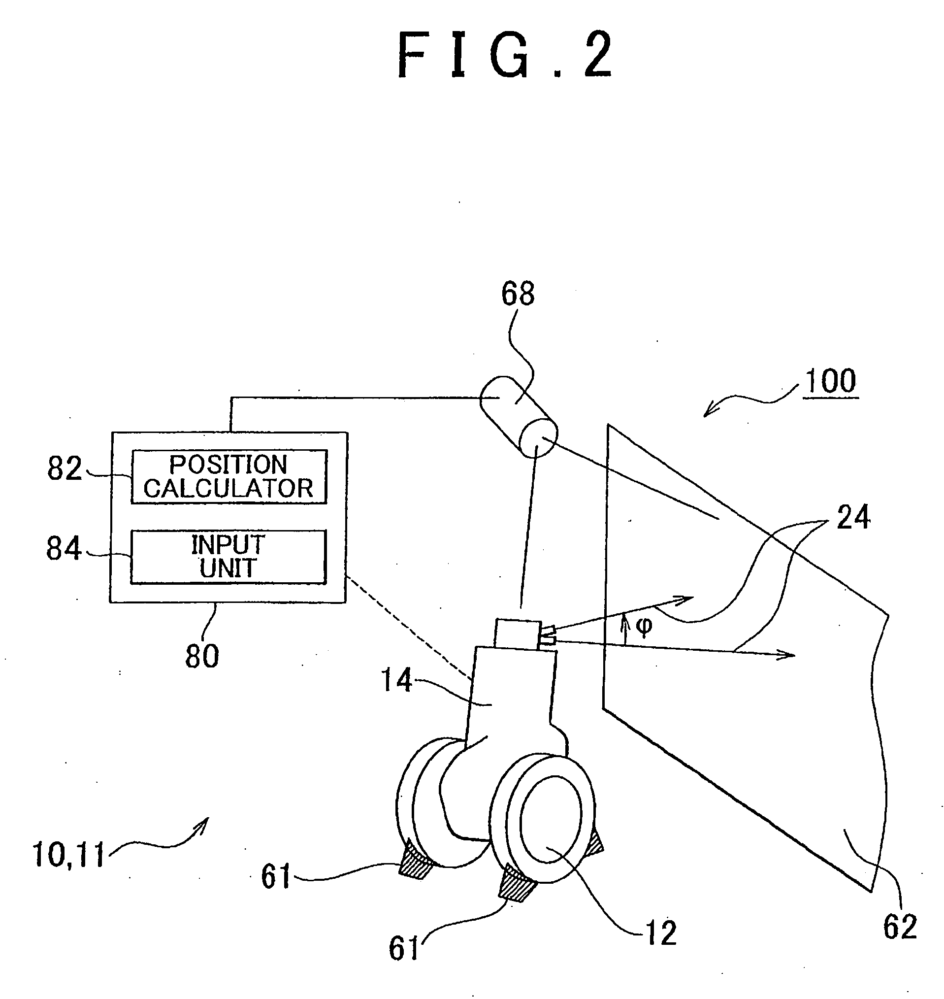
[0043]An embodiment of the present invention is explained with reference to the drawings. In the following description, an optical gyro, which includes an optical element, is used for the positioning control of a robot. However, a gyro other than an optical gyro may be used if such a gyro has the precision / accuracy sufficient for the positioning control of the robot. The robot in the following description is a robot for the purpose of entertainment. However, a robot for other purposes may be used, if such a robot has a gyro. In addition, in the following description, the calibrator is a part of a robot controller provided in the robot. However, the calibrator may be a separate device that is not mounted on the robot and may be linked with the robot by a wired or a wireless connection. An indicator may also be mounted on the robot in the following description, but the invention does not exclude a separate device that is not mounted on the robot and which may be linked with the robot ...


PUM


Abstract

While calibrating the position of a robot having a gyro, the robot emits a beam of light to a target wall surface, and the position of a laser point on the target wall surface illuminated by the beam of light is measured. The measured position is obtained as an initial value (S10, S12), and a start of calibration is indicated (S14, S16). Then, a calibration period is reset (S18) and the timekeeping process of the calibration period starts. The values detected by the gyro are consecutively obtained by sampling for a predetermined calibration period (S20). If a disturbance occurs while the values are obtained, an alarm is output and calibration restarts. Once the calibration period elapses without any disturbance, a calibrated value is set or determined based on the detected values obtained during the calibration period (S26, S28).

Description

BACKGROUND OF THE INVENTION[0001]1. Field of the Invention[0002]This invention relates to, a robot equipped with a gyro and a gyro calibration apparatus, program, and method. In particular, this invention relates to the calculation of positional information in a robot that equipped with a gyro based on values detected by the gyro, a gyro calibration apparatus and a method that calibrates the gyro, and a gyro calibration program.[0003]2. Description of the Related Art[0004]Mobile robots, such as bipedal robots (robot walking with two legs) or mobile robots for the purpose of entertainment, are known. To move to a target position, such robots detect or calculate changes in the position of the robot over time. Generally, such technology is known as a position-detecting method of a mobile object, and various approaches may be taken to improve the precision / accuracy of the position detection.[0005]For example, JP-A-07-286858 describes an obstacle detection apparatus installed on a vehicl...

Claims


Application Information

Patent Timeline
IPC IPC(8): G01C25/00
CPCG01C19/00G05D1/0891G01C25/00
Inventor MORI, TAKEMITSUKATO, TAKASHINONOMURA, YUTAKAFUJIYOSHI, MOTOHIRO
Owner TOYOTA JIDOSHA KK
Why Eureka
Try Eureka