Rotating Nut Ball Screw Unit with Lubricating Arrangement

Active Publication Date: 2009-05-28
HIWIN TECH
View PDF6 Cites 20 Cited by
  • Summary
  • Abstract
  • Description
  • Claims
  • Application Information

AI Technical Summary

Benefits of technology

[0010]Accordingly, it is the main object of the present invention to provide a rotating nut ball screw unit wi

Problems solved by technology

However, this structure is inapplicable to the rotating nut ball screw unit since the lubricant box attached to the nut will rotate along with t

Method used


Image

  • Rotating Nut Ball Screw Unit with Lubricating Arrangement
  • Rotating Nut Ball Screw Unit with Lubricating Arrangement
  • Rotating Nut Ball Screw Unit with Lubricating Arrangement

Examples


Example

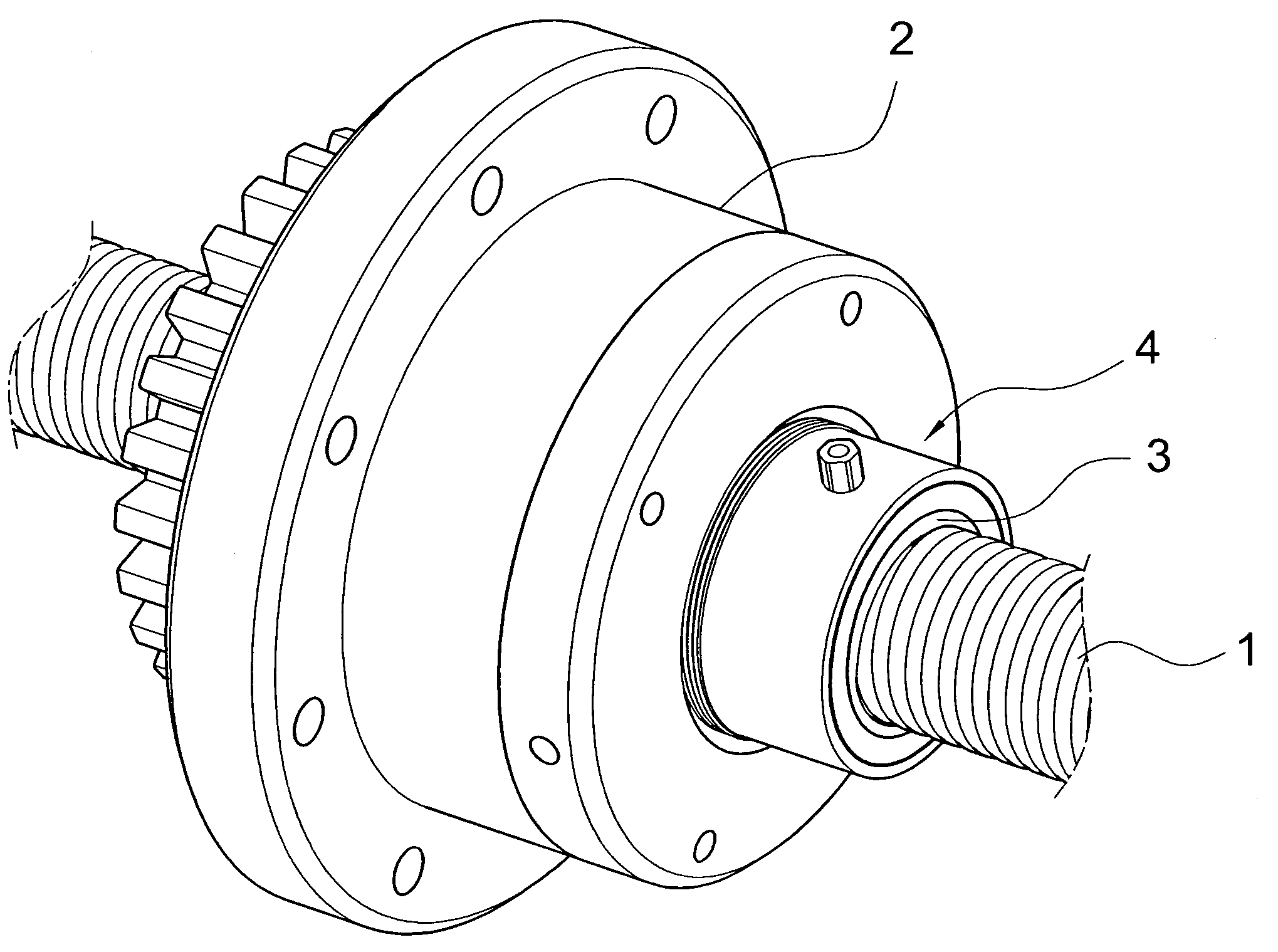
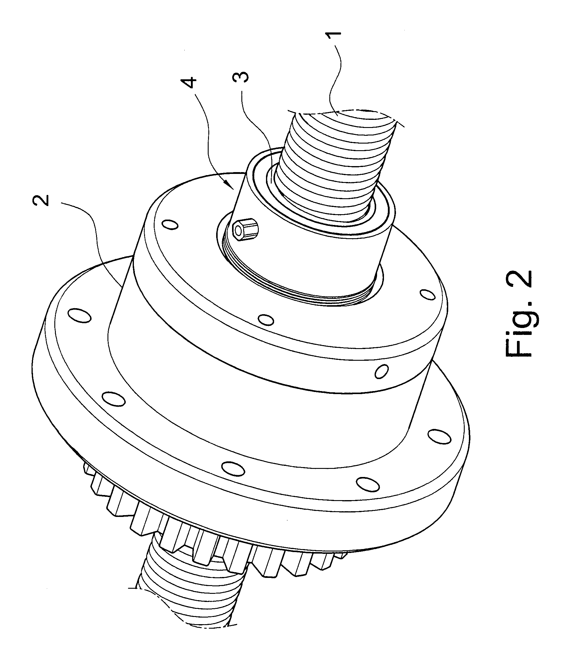
[0024]Referring to FIG. 2 through FIG. 6, the rotating nut ball screw unit with lubricating arrangement of the present invention is composed of the following component parts:

[0025]a screw bolt 1 with an outer threaded surface 11, and

[0026]a rotating nut unit 2 comprising a nut 22, several split bearings 23 and a bearing shell 21. The nut 22 is hollow and encircling the screw bolt 1, the inner surface of the nut 22 is provided with an inner spiral groove 221 corresponding to the outer threaded surface 11 of the screw bolt 1. The bearings 23 are disposed to support the nut 22 and enclosed by a bearing shell 21 such that the nut 2 can rotated against the bearing shell 21 with the split bearings 23 intercalated therebetween.

[0027]A plurality of balls X are interposed between the outer threaded surface 11 of the screw bolt 1 and the inner spiral groove 221 of the nut 22.

[0028]An oil storage (not shown) communicated with an oil outlet 46 is provided for supplying the lubricant.

[0029]A lub...


PUM


Abstract

The rotating nut ball screw unit with lubricating arrangement has a lubricating device composed of a main body, a collar and a bearing. The main body is provided with several oil holes and is attached to the end surface of the nut. The main body is relatively rotatable with respect to the collar intercalating the bearing therebetween. An oil storage forces the lubricant into an oil reserving space surrounded by the main body, the collar and the bearing. The oil reserving space is in communication with the oil holes and allows the lubricant to be forced into the main body and then to reach the surface of the screw bolt via oil holes. The forced lubrication arrangement of the present invention ensures a better lubricating effect.

Description

BACKGROUND OF THE INVENTION[0001]1. Field of the Invention[0002]The present invention relates to a rotating nut ball screw unit, and more particularly, to a rotating nut ball screw unit having a lubricating device.[0003]2. Description of the Prior Art[0004]In a rotating nut ball screw unit, the nut and the bearing shell is formed in one piece. The bearing shell is engaged with a working table, and the mechanical power is transmitted to the nut from a motor with a belt conveyer so as to drive the nut to rotate against the stationary screw bolt thereby removing the working table in the axial direction. As the screw bolt does not move, it is free from the problematic rotational inertia that causes a slender ball screw unit able to work with a high speed easily using a relatively small motor. With this merit, it is specially preferable to the semiconductor industry, the wood working machine, and the conveyance work that are considered to be modern and very important industries nowadays....

Claims


Application Information

Patent Timeline
IPC IPC(8): F16H25/22F16H57/04
CPCF16H57/0497Y10T74/18736Y10T74/18744
Inventor CHEN, XIN-HETSAI, CHIEH-HUNGHSIEH, WU-TENG
Owner HIWIN TECH
Why Eureka
Try Eureka