Heat exchanger

Inactive Publication Date: 2009-05-28
DENSO CORP
View PDF9 Cites 29 Cited by
  • Summary
  • Abstract
  • Description
  • Claims
  • Application Information

AI Technical Summary

Benefits of technology

[0006]In view of the foregoing problems, it is an object of the present invention t

Problems solved by technology

As shown in FIG. 8, high-temperature intake air flowing from the intake air inlet of the tube into the tube is drastically cooled in the tube, resulting in a large difference in temperature of the intake air between the intake air inlet side and the intake air outlet side of the tube.
At this time, the use of the inner fins with the same specification from the intake air inlet side to the outlet side as described above may drastically increase the loss in pressure at the intake air inlet side, resulting in reduct

Method used


Image

  • Heat exchanger
  • Heat exchanger
  • Heat exchanger

Examples


Example

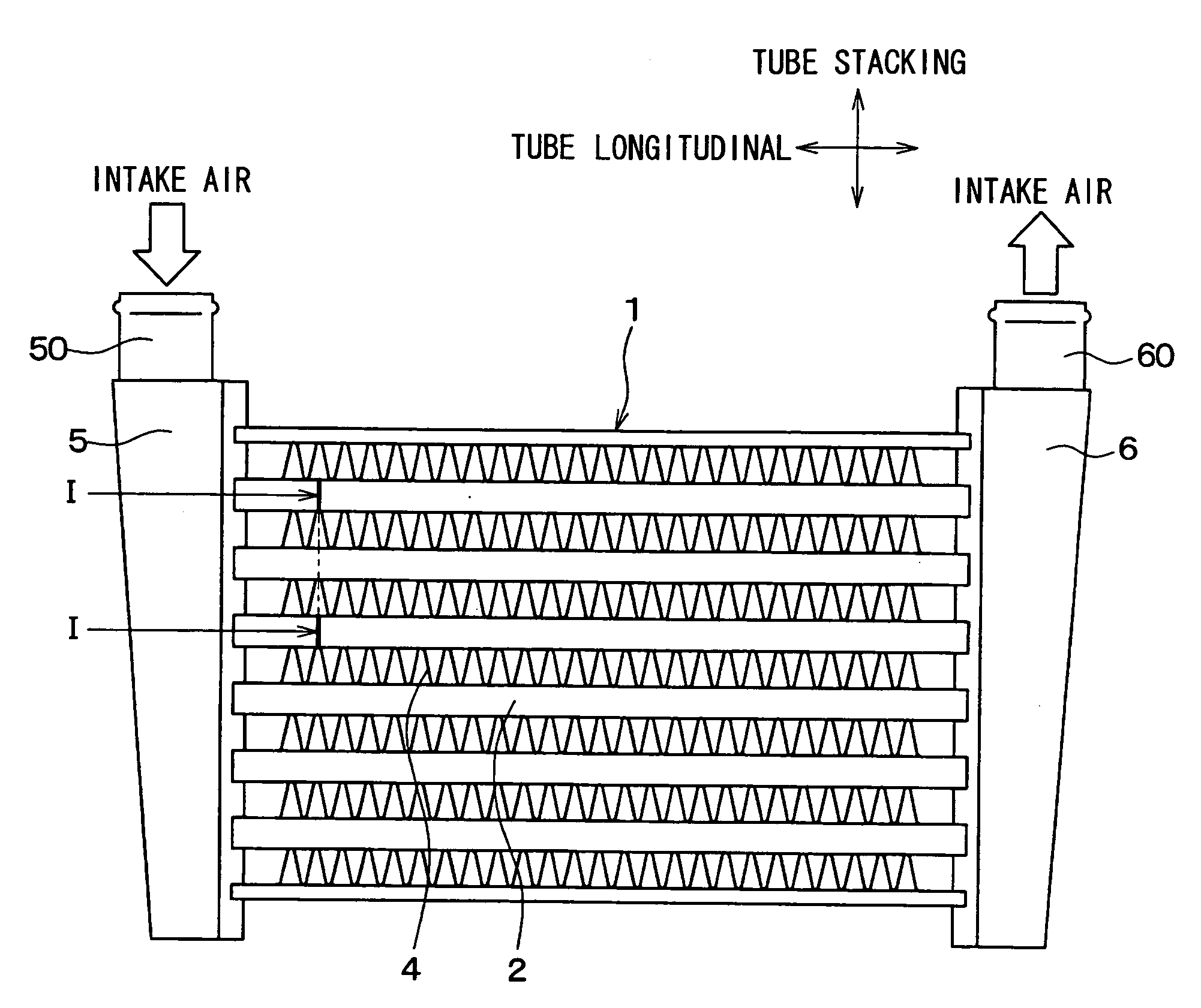
[0028]A first embodiment of the present invention will be described below with reference to FIGS. 1 to 4. A heat exchanger according to the first embodiment of the present invention is typically used for an intercooler. The intercooler is configured to perform heat exchange between outside air (cooling air) and intake air for combustion to be supplied into an internal combustion engine, thereby to cool the intake air. The intake air is an example of a first fluid of the present invention, and the cooling air is an example of a second fluid of the present invention.

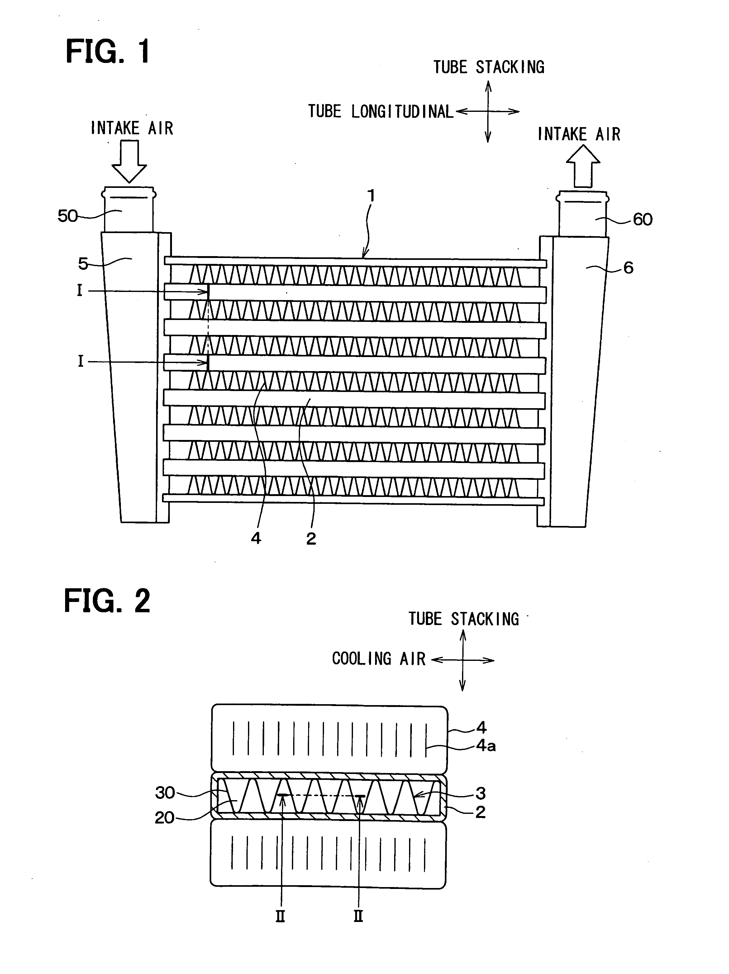
[0029]As shown in FIGS. 1 and 2, a core portion 1 of the intercooler includes a plurality of stacked flat tubes 2 each having a flow passage formed therein for allowing intake air to flow therethrough, inner fins 3 disposed within the flat tubes 2, and outer fins 4 each of which is disposed between the stacked flat tubes 2. The flat tubes 2 are stacked in a tube stacking direction that is perpendicular to the tube longitud...

Example

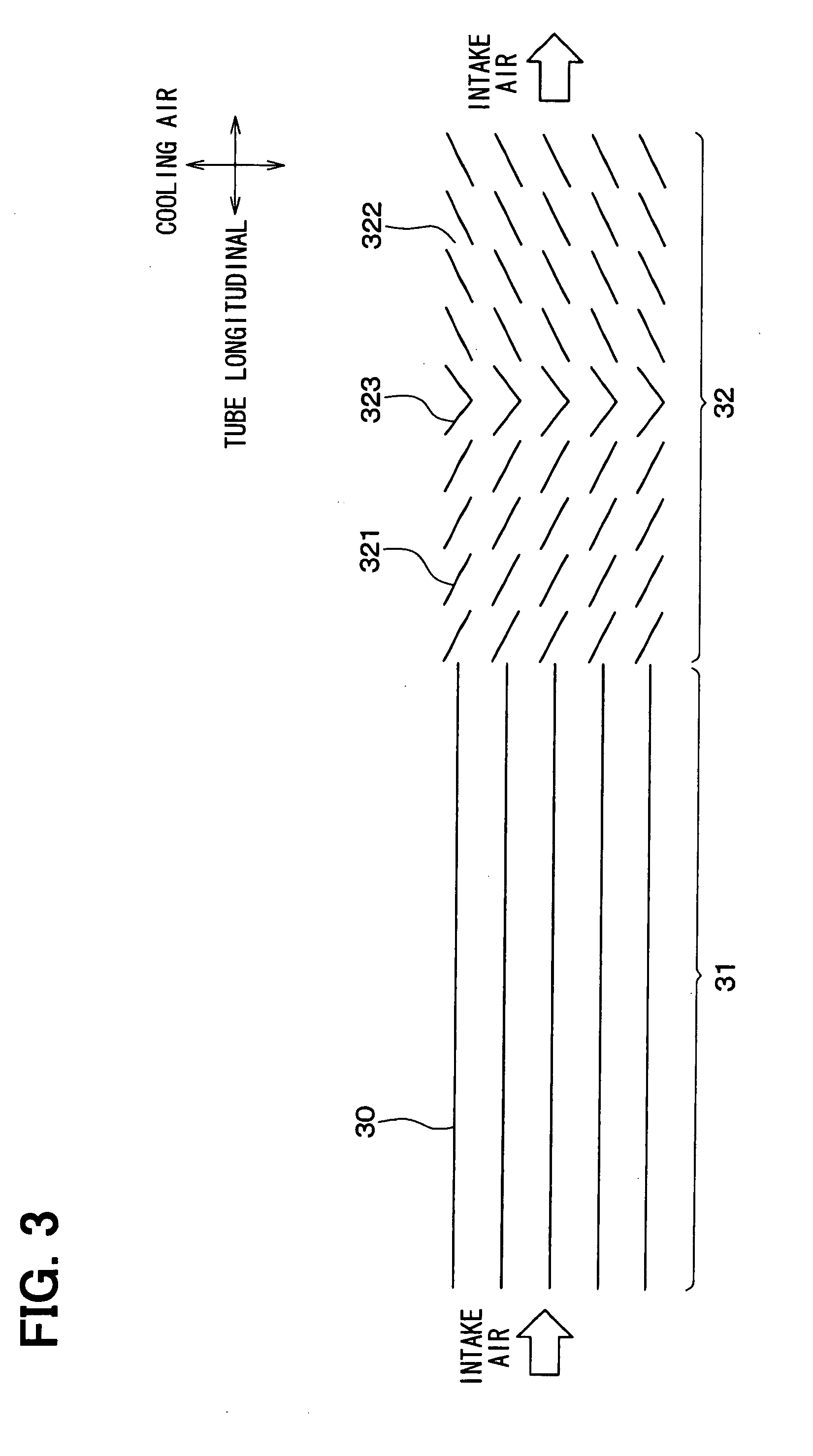
[0045]A second embodiment of the present invention will be described below based on FIGS. 5 and 6. The same components as those in the first embodiment are designated by the same reference numerals, and a description thereof will be omitted below. FIG. 5 is a sectional view of the inner fin 3 of the second embodiment when being viewed in the stacking direction of the tubes 2. FIG. 5 of the second embodiment is a drawing corresponding to FIG. 3.

[0046]As shown in FIG. 5, an inter fin 3 of the present embodiment includes three different kinds of fin portions 31 to 33. The three fin portions 31 to 33, namely, the first fin portion 31, the third fin portion 33, and the second fin portion 32 are arranged continuously in that order from the upstream side of the intake air flow. The first fin portion 31 is a straight fin similar to that in the first embodiment. The second fin portion 32 is a louver fin similar to that in the first embodiment.

[0047]FIG. 6 is an enlarged perspective view show...

Example

Third Embodiment

[0051]A third embodiment of the present invention will be described below based on FIG. 7. The same components as those in the first embodiment are designated by the same reference numerals, and a description thereof will be omitted below. FIG. 7 is a sectional view showing an inner fin 3 of the third embodiment when being viewed in the stacking direction of tubes 2. FIG. 7 is a diagram corresponding to the diagram of FIG. 3.

[0052]As shown in FIG. 7, the inner fin 3 of the present embodiment includes two first fin portions 31 each of which is a straight fin similar to that of the first embodiment, and a second fin portion 32 which is a louver fin similar to that of the first embodiment. The two first fin portions 31 are disposed one by one on the upstream and downstream sides of the second fin portion 32 in the flow direction of intake air. In other words, the second fin portion 31is disposed between the two first fin portions 31 in the flow direction of the intake a...


PUM


Abstract

In a heat exchanger, a tube is adapted to exchange heat between a first fluid flowing therein and a second fluid flowing through outside of the tube, and an inner fin is disposed in the tube to divide a flow passage in the tube into a plurality of flow paths. The inner fin includes a plurality of fin portions with different specifications, and the fin portions are arranged in series with respect to a flow direction of the first fluid. Furthermore, the fin portion with the smallest flowing resistance of the first fluid among the plurality of fin portions is arranged on an upstream side of the flow direction of the first fluid with respect to at least an another fin portion. Accordingly, heat exchange performance in the entire heat exchanger can be effectively improved.

Description

CROSS REFERENCE TO RELATED APPLICATION[0001]This application is based on Japanese Patent Application No. 2007-303289 filed on Nov. 22, 2007, the contents of which are incorporated herein by reference in its entirety.FIELD OF THE INVENTION[0002]The present invention relates to a heat exchanger. The heat exchanger can be suitably used as an intercooler for cooling intake air to be supplied to an internal combustion engine, for example.BACKGROUND OF THE INVENTION[0003]Conventionally, a heat exchanger such as an intercooler performs heat exchange between cooling air and intake air to be drawn into an internal combustion engine so as to cool the intake air (for example, JP-A-2006-90305). The intercooler includes inner fins inserted into tubes in which the intake air flows, thereby promoting heat exchange between the intake air and the cooling air. The inner fins have generally the same shape, that is, the same specification from an intake air inlet side of the tubes to an intake air outl...

Claims


Application Information

Patent Timeline
IPC IPC(8): F28D7/00
CPCF28D1/05366F28F1/40F28F1/128F28D2021/0082
Inventor HARADA, MASAKISUSA, SUMIOWATANABE, HARUHIKO
Owner DENSO CORP
Why Eureka
Try Eureka