Heat exchanger
A technology of heat exchangers and fins, which is applied in the field of heat exchangers, can solve the problems of light weight or miniaturization of heat exchangers, difficulty in checking leaks at joints, difficulty in bending with small curvature radii, etc., and achieves simple manufacturing technology, Excellent heat exchange performance, simplification of manufacturing technology or effect of manufacturing process
- Summary
- Abstract
- Description
- Claims
- Application Information
AI Technical Summary
Problems solved by technology
Method used
Image
Examples
Embodiment 1
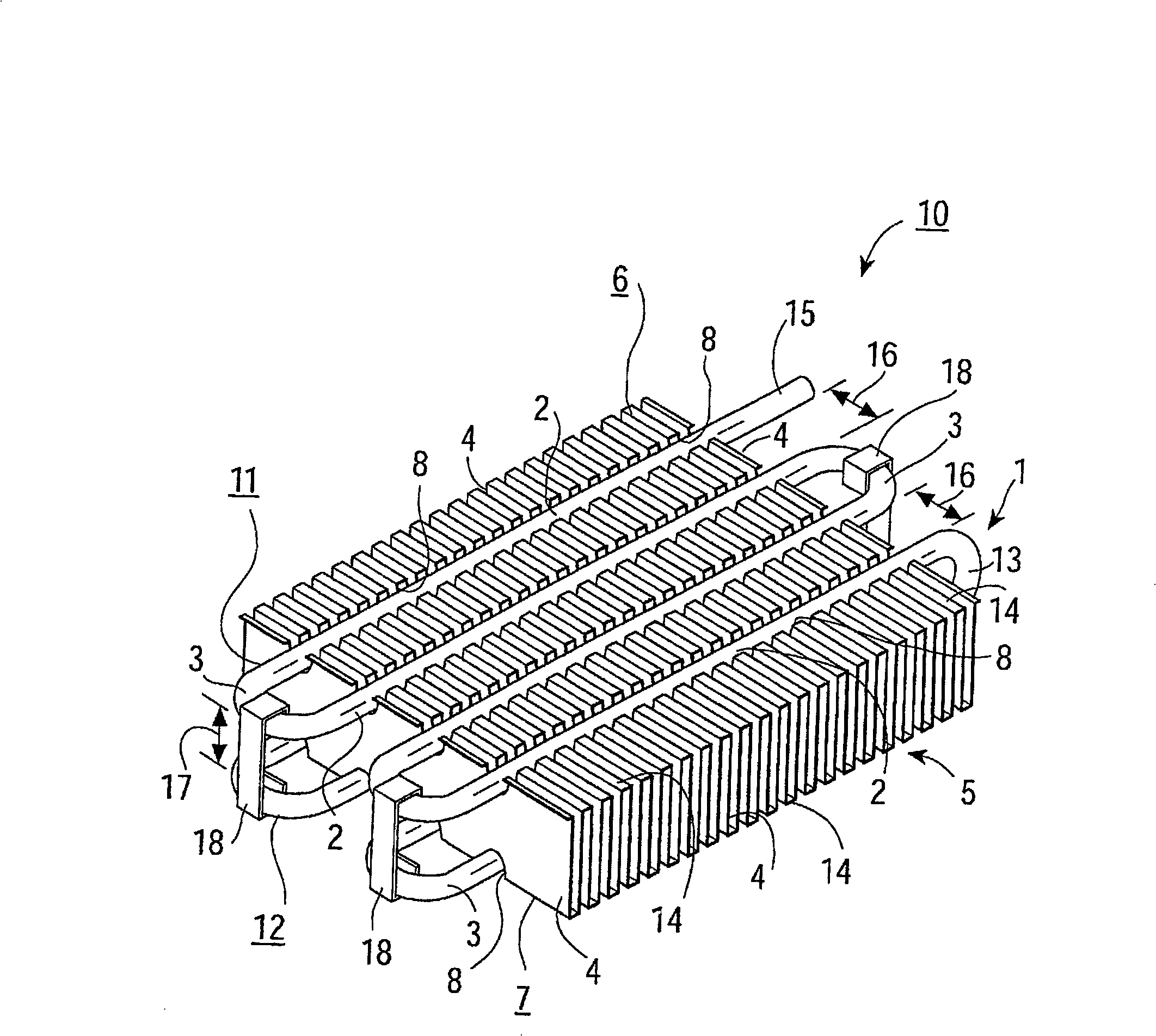
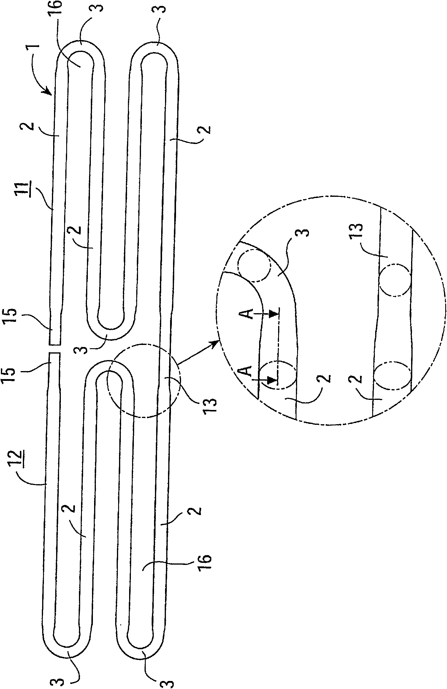
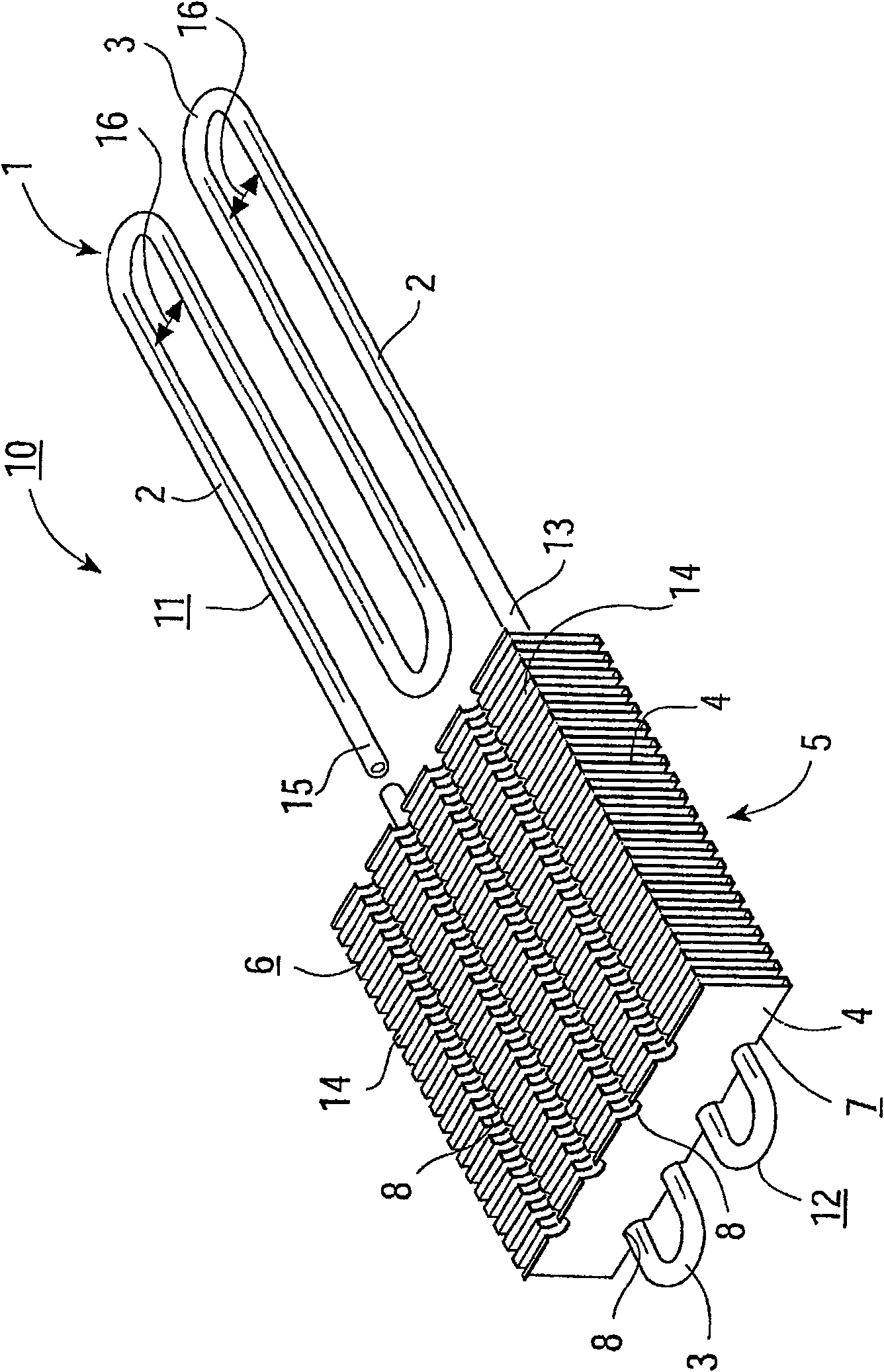
[0098] Embodiment 1 in which the heat exchanger of the present invention is implemented as a fuel pipe arranged under the floor of an automobile is utilized Figure 1 to Figure 6 To describe it in detail, 1 is the main body of the meandering pipe, and a pair of meandering parts 11 and 12 are arranged to face each other with the insertion gap 17 of the fin member 5 separated therebetween. A plurality of straight pipe portions 2 arranged in parallel at intervals 16 and a bent portion 3 connecting the plurality of straight pipe portions 2 are formed. Furthermore, in the insertion gap 17 formed between the serpentine part 11 of the one group and the serpentine part 12 of the other group, the fin member 5 is inserted and disposed, and the fin member 5 is arranged on two opposite sides of the plurality of cooling fins 4 arranged in parallel. A plurality of rectangular engaging grooves 8 are provided at regular intervals on the end faces 6 and 7 , and a heat exchanger 10 is formed by...
Embodiment 2
[0113] In the above-mentioned embodiment 1, a metal pipe is bent to form a serpentine pipe main body 1 composed of a plurality of straight pipe parts 2, bent parts 3, and connecting pipes 13, etc., but in another different embodiment 2 Among them, the bent portion 3 and the connecting pipe 13 are formed by a U-shaped ventilation pipe, and a plurality of straight pipe portions 2 are formed by a single straight pipe. Furthermore, the plurality of straight pipe parts 2 are arranged at an opposing interval 16, and the straight pipe parts 2 are connected by the bent part 3, and connected to each other by brazing or welding to form a pair of meandering parts 11, 12, respectively. Furthermore, a pair of meandering parts 11 and 12 arranged to face each other are connected by a connecting pipe 13 with an insertion gap 17 of the fin member 5 interposed therebetween. In addition, in order to facilitate arrangement in the engaging groove 8, the straight pipe portion 2 is formed into an el...
Embodiment 3
[0117] In addition, in Embodiments 1 and 2, the fixing of the straight pipe portion 2 to the engaging groove 8 is performed by the clamping force between one serpentine portion 11 and the other serpentine portion 12, and the clamping and fixing force of the clip 18. of. In order to make the fixing between the straight pipe part 2 and the engaging groove 8 more firm, in embodiment 3, when it is arranged in the engaging groove 8, as Figure 8 As shown, the straight pipe portion 2 is formed in an elliptical shape, the short diameter portion of the ellipse is smaller than the width of the engagement groove 8 , and the long diameter portion of the ellipse is larger than the width of the engagement groove 8 . Furthermore, when the elliptical straight pipe part 2 is arranged in the engagement groove 8, as Figure 8 As shown, it is arranged so that the major diameter of the ellipse is located in the direction of the bottom of the engaging groove 8 and the opening. Moreover, since th...
PUM
 Abstract
Description
Claims
Application Information
 - R&D
- Intellectual Property
- Life Sciences
- Materials
- Tech Scout
- Unparalleled Data Quality
- Higher Quality Content
- 60% Fewer Hallucinations
Browse by: Latest US Patents, China's latest patents, Technical Efficacy Thesaurus, Application Domain, Technology Topic, Popular Technical Reports.
© 2025 PatSnap. All rights reserved.Legal|Privacy policy|Modern Slavery Act Transparency Statement|Sitemap|About US| Contact US: help@patsnap.com


