Miniaturized and light-weight Ka waveband space traveling wave tube

A light-weight, traveling wave tube technology, applied in the field of traveling wave tubes, can solve the problems of high manufacturing and launch costs of the entire satellite, increasing the volume and weight of the entire satellite, unfavorable expansion of the commercial market, etc., and achieve less welding leakage. The effect of reducing the risk of gas, reducing the difficulty of processing, improving welding concentricity and reliability

Active Publication Date: 2019-12-27
NANJING SANLE GROUP
View PDF8 Cites 2 Cited by
  • Summary
  • Abstract
  • Description
  • Claims
  • Application Information

AI Technical Summary

Problems solved by technology

With the rapid development of low-orbit communication satellites, higher requirements are put forward for the miniaturization and popularization of satellites. The original traveling wave tube is large in size and heavy in weight, which increases the size and weight of the entire satellite. The high launch cost is not conducive to the expansion of the commercial market, so there is an urgent need for breakthroughs in the development of miniaturized and light-weight traveling wave tubes
Since the space traveling wave tube must have high energy conversion efficiency, meet the requirements of output power and gain, output with smaller harmonic components and third-order intermodulation components, as well as smaller phase distortion and smaller group delay At the same time, satellite systems require space traveling wave tubes used in orbit to meet the requirements of ≥ 12 years of life, and the development of space traveling wave tubes needs to meet stringent requirements. Although space traveling wave tubes are miniaturized, these requirements cannot reduced, greatly increasing the difficulty of development

Method used


Image

  • Miniaturized and light-weight Ka waveband space traveling wave tube
  • Miniaturized and light-weight Ka waveband space traveling wave tube
  • Miniaturized and light-weight Ka waveband space traveling wave tube

Examples


Embodiment Construction

[0025] Below in conjunction with accompanying drawing and specific embodiment, further illustrate the present invention, should be understood that these embodiments are only for illustrating the present invention and are not intended to limit the scope of the present invention, after having read the present invention, those skilled in the art will understand various aspects of the present invention Modifications in equivalent forms all fall within the scope defined by the appended claims of this application.

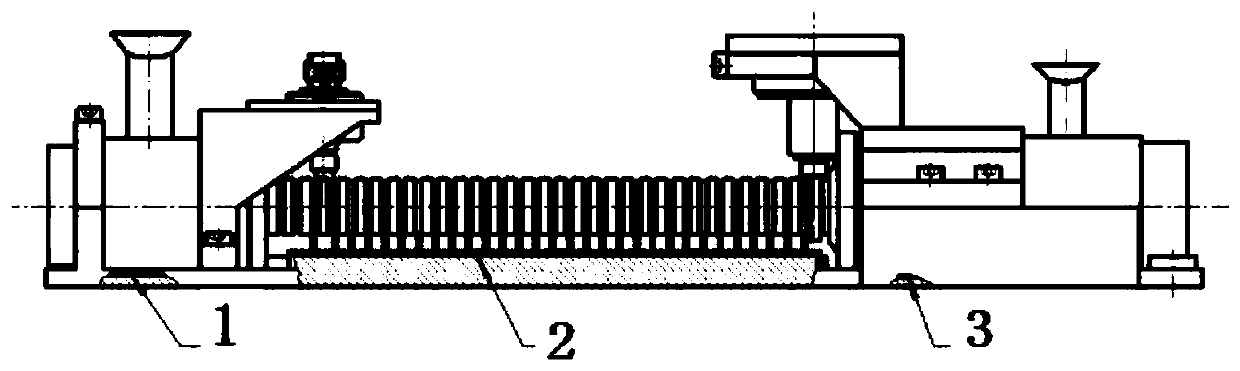
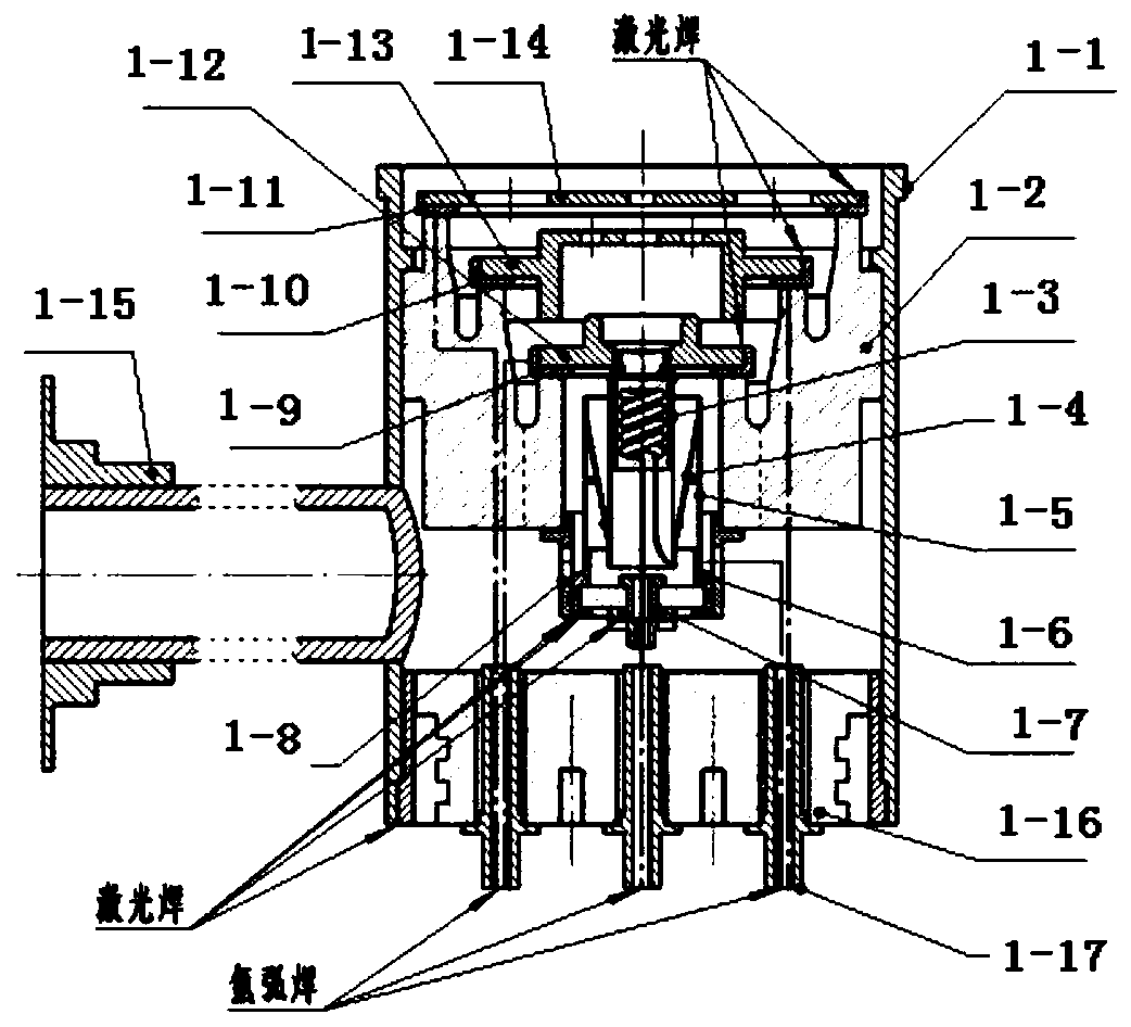
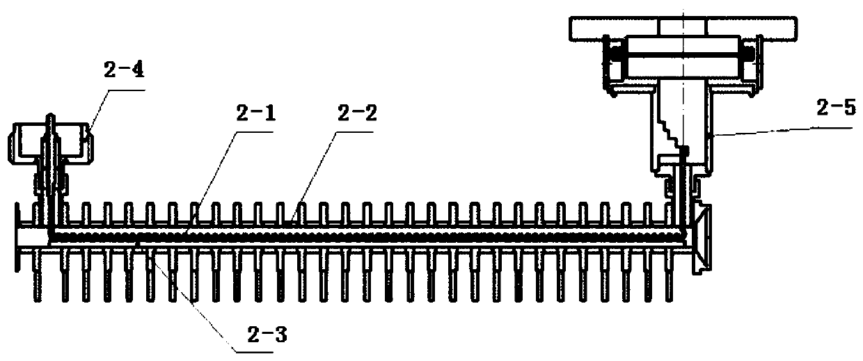
[0026] Such as Figure 1 to Figure 4 As shown, a miniaturized, light-weight Ka-band space traveling wave tube includes: a double-anode electron gun 1, a helical slow-wave circuit 2 connected with the double-anode electron gun 1, and a four-phase helical slow-wave circuit connected with the helical slow-wave circuit 2 Step-down collector 3;

[0027] The double-anode electron gun 1 includes a metal electron gun shell 1-1, an integrated porcelain 1-2 installed inside the m...


PUM


Abstract

The invention discloses a miniaturized and light-weight Ka waveband space traveling wave tube. The traveling wave tube comprises a double-anode electron gun (1), a spiral line slow wave circuit (2) connected with the double-anode electron gun (1), and a four-stage step-down collector (3) connected with the spiral line slow wave circuit (2). The device is reasonable in structural design, high-performance miniaturized electron guns are screened out through a large number of experiments, the spiral line slow wave circuit has high linearity and high efficiency, the whole pipe heat dissipation structure is for rapid cooling, and the four-stage depressed collector is excellent in heat exchange performance and low in backflow. The device is advantaged in that experimental detection results show that the total length of the traveling wave tube is smaller than 200 mm, the weight is smaller than 350 g, the power is larger than 55 W, the work ratio is 100%, the phase shift curve is monotonous andsmaller than 45 degrees, third-order intermodulation is larger than 18.5 dBc, and the traveling wave tube has excellent performance, good work stability and a wide application range.

Description

technical field [0001] The invention relates to a traveling wave tube, in particular to a Ka-band space traveling wave tube with high output efficiency, miniaturization and light weight. Background technique [0002] Satellites have a wide range of uses, including military confrontation, reconnaissance, radar applications, commercial communications, broadband multimedia, meteorological applications, navigation and communications, etc., which have effectively promoted the development of various undertakings. Space traveling wave tube amplifier, as a common option for final power amplification, has attracted much attention. Space traveling wave tubes are generally used as the core components of various application satellites abroad. With the rapid development of low-orbit communication satellites, higher requirements are put forward for the miniaturization and popularization of satellites. The original traveling wave tube is large in size and heavy in weight, which increases t...

Claims


Application Information

Patent Timeline
Patent Type & Authority Applications(China)
IPC IPC(8): H01J25/34H01J23/027H01J23/033H01J23/06H01J23/27
CPCH01J23/0275H01J23/033H01J23/06H01J23/27H01J25/34
Inventor 刘颖博孙萌胥辉成红霞丁未张欣玲冯西贤
Owner NANJING SANLE GROUP
Why Eureka
Try Eureka