Heat transfer pipe with radiating fin parts

一种散热片、传热管的技术,应用在传热管领域,能够解决不能很好地实现散热片部件金属管的外周面紧密接合、不能获得金属管和散热片部件传热性、散热特性和吸热特性有问题等问题,达到良好热交换性能、保持热交换性能、提高耐冲击性的效果

Inactive Publication Date: 2005-03-09
USUI CO LTD
View PDF6 Cites 2 Cited by
  • Summary
  • Abstract
  • Description
  • Claims
  • Application Information

AI Technical Summary

Problems solved by technology

[0012] However, in the heat transfer tubes provided with the resin coating layer of Patent Documents 1 and 2, the thick resin coating layer formed in order to improve impact resistance and corrosion resistance has problems in heat dissipation and heat absorption characteristics, and it is difficult to improve the heat transfer performance. The heat exchange efficiency between the fluids flowing inside and outside the heat pipe
[0013] On the other hand, the protrusions of Patent Documents 3 to 5 are provided with heat transfer tubes made of metal material fin parts, which increases the heat transfer area and can obtain higher heat exchange performance, but the anti-corrosion coating on the surface of the metal tube is easily damaged by flow stone There is a problem in corrosion resistance due to damage due to waiting
In addition, since the fin member formed of a flat metal material and the contact portion of the metal tube are provided with corrugations, etc., and formed into a helical shape and wound on the metal tube, the spiral is generated due to the restoring force of the metal material. Twisted, the contact part of the heat sink part and the outer peripheral surface of the metal tube cannot be well bonded, and a gap is generated so that good heat transfer between the metal tube and the heat sink part cannot be obtained
[0014] In order to prevent this twisting, the two ends of the spiral fin member are fixed to the metal tube by clip fixing or screw fixing, etc., but in the manufacturing process, not only it takes a lot of man-hours, but also the gap between the fin member and the metal tube The fixation alone is not sufficient for contact
Therefore, it is necessary to close the gap between the heat sink member and the metal pipe by painting or brazing, and the work process is cumbersome, and it is difficult to improve production efficiency.

Method used


Image

  • Heat transfer pipe with radiating fin parts
  • Heat transfer pipe with radiating fin parts
  • Heat transfer pipe with radiating fin parts

Examples


Embodiment 1

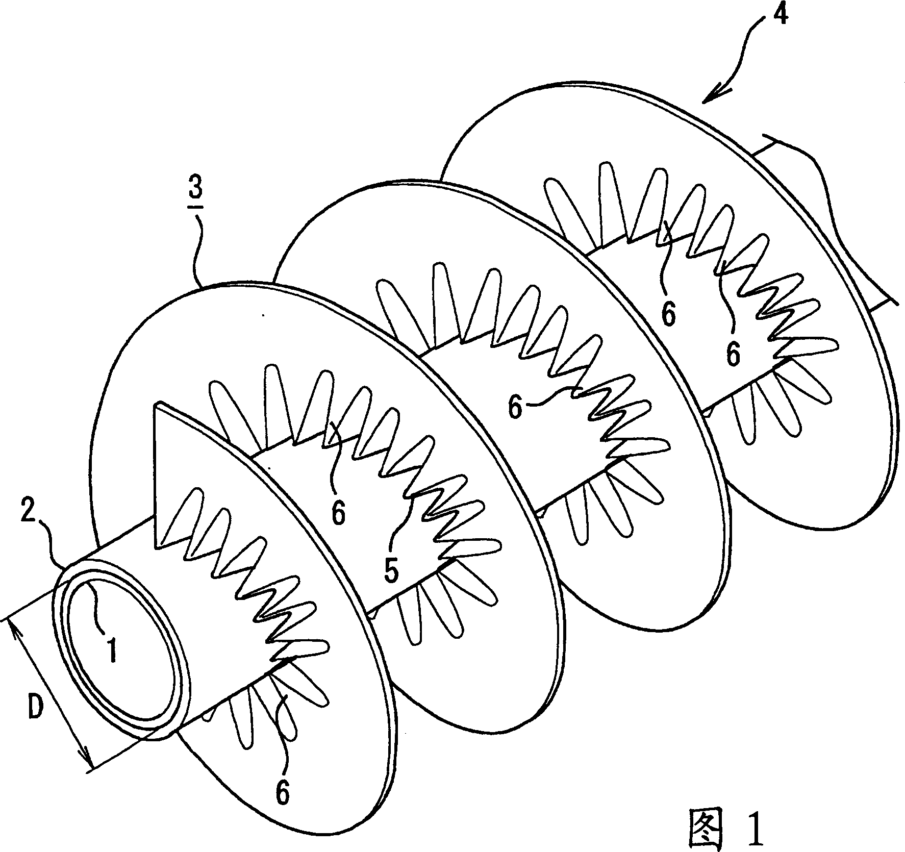
[0062] First, let’s describe Figures 1 to 1 in detail. Figure 4 The shown embodiment 1, 1 represents a metal pipe, using a single-layer wound steel pipe with an outer diameter of 8mm, a wall thickness of 0.7mm, and no copper plating on the outer surface, a composite wound steel pipe, an aluminum pipe, etc. with a copper outer surface. This metal pipe 1 can obtain corrosion resistance by setting the resin film layer 2 as described later, so it can be used directly, but in this embodiment, an alternative corrosion-resistant coating ( not shown), it can exhibit good corrosion resistance even in harsh corrosive environments.

[0063] The above-mentioned anti-corrosion coating can be a layer of coatings such as zinc, tin, tin-zinc alloy, nickel, zinc-nickel alloy, zinc-aluminum alloy, etc., and can also be nickel-plated on the outer surface of the metal pipe 1). The outer peripheral surface is plated with zinc-nickel alloy to form a multi-layer coating such as a two-layer structu...

Embodiment 2

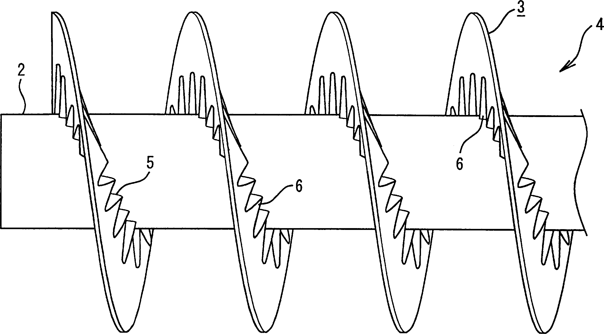
[0081] In the above-mentioned Embodiment 1, before the fin member 3 provided with the corrugated corrugations 6 covering the entire width is prepared to be installed on the metal tube 1, the fin member 3 is wound in a helical shape on the outer periphery of the metal tube 1 easily. , and the diameter of the inner peripheral side is reduced to increase the undulation of the corrugated pleats 6, and the corrugated pleats 6 on the outer peripheral side are stretched and formed into a flat shape, and the fin member 3 is curved into an arc shape. In contrast, in Example 2, as Figure 6 As shown, the heat sink member 3 provided with a plurality of corrugated corrugations 6 over the entire width is wound on the metal tube 1 in a spiral shape, while the inner peripheral side is reduced in diameter and the undulations of the corrugated corrugations 6 are increased. on the peripheral side as Figure 6 As shown, the corrugated pleats 6 are not stretched into a flat shape, but only the p...

Embodiment 3

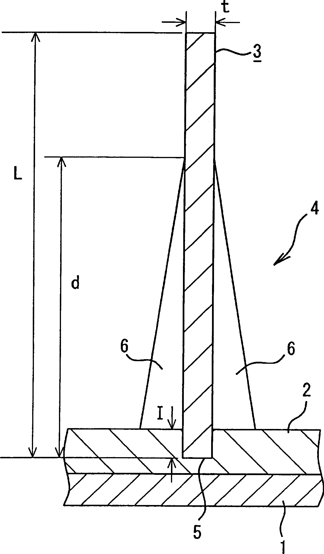
[0086] exist Figure 7 In Example 3 shown, the cationic electrodeposition coating is applied to the entire outer surface of the heat transfer tube 4 . In the process of making the heat transfer tube 4, first, the outer circumference of the iron metal tube 1 is electroplated with zinc series to improve corrosion resistance, and after the epoxy resin as a primer is provided on the outer circumference, the outer circumference of the epoxy resin is PA is extruded to form the resin coating layer 2 . Then, on the outer periphery of the metal pipe 1 provided with the resin film layer 2, the iron fin member 3, which is electroplated with zinc to improve corrosion resistance, is provided in a spiral shape to form the heat transfer pipe 4. The helical configuration of the heat sink component 3 can be Figure 4 When the shown fin member 3 provided with corrugated corrugations 6 covering the entire width is wound on the metal tube 1, as Figure 5 As shown in Example 1, it is arranged w...


PUM


Abstract

It is an object of this invention to obtain a heat conduction pipe superior in corrosion resistance as well as heat exchange efficiency between fluid flowing respectively through an inside and an outside for great heat radiation property and endothermic characteristics. It is also object of this invention to form the heat conduction pipe superior in the corrosion resistance as well as the heat radiation property and endothermic characteristics at inexpensive price. To achieve the above, at least single resin coating layer is formed on an outer circumferential surface of a metal pipe, a metal fin member is spirally wound on an outer circumferential surface of the resin coating layer with a side end surface the metal fin member in contact. The winding contact portion is made to encroach a surface of the resin coating layer to form the heat conduction pipe.

Description

technical field [0001] The present invention relates to heat transfer pipes that can be used in fluid cooling pipes for automobiles and construction machinery, air conditioners that adjust the temperature and humidity of residential spaces, and other equipment, and have corrosion resistance that can be used in corrosive environments. The heat transfer tube obtained by the invention not only has good corrosion resistance, but also can perform effective heat exchange with high heat dissipation and heat absorption characteristics. Background technique [0002] Conventionally, as heat transfer tubes having corrosion resistance, there have been heat transfer tubes as described in the following Patent Documents 1 and 2, and metal tubes such as steel tubes or aluminum tubes that have been coated with corrosion-resistant coatings such as galvanized or chromate coatings have been used. The outer peripheral surface of the tube is provided with a thermoplastic resin film layer such as ...

Claims


Application Information

Patent Timeline
Patent Type & Authority Applications(China)
IPC IPC(8): F16L53/00F16L9/00F28F1/10F28F1/32F28F1/36F28F13/18F28F19/04F28F21/06F28F21/08
CPCF28F1/36F16L9/006F28F19/04F28F13/185F28F1/10F28F1/32
Inventor 桥本康明四元众
Owner USUI CO LTD
Why Eureka
Try Eureka